
Lazer Tag Infrared Receivers

To understand how these taggers operate, it is important to note that they do not utilize lasers for hit transmission; instead, they employ infrared (IR) LEDs, akin to infrared TV remotes. The system resembles a TV remote and receiver, equipped with optics to maintain a narrow beam. Players must utilize the iron sights for accurate targeting, enhancing the realism of the gameplay. However, the design includes limitations, such as the IR receiver being mounted on the gun rather than the player, allowing for potential cheating and diminishing the immersive experience.
The individual aimed to explore the IR receiver further and assess the feasibility of integrating external sensors. Previous disassembly revealed challenges with the IR receiver circuit, including difficulties in module disassembly without causing damage. As this particular tagger was an outlier in their collection, the individual decided to reverse engineer its schematic. The red LEDs, which are controlled separately from the IR receiver, were excluded from this analysis. The indoor mode function adjusts the receiver sensitivity by varying the bias on the PIN photodiodes.
The primary integrated circuit (IC) is obscured by an epoxy blob, but its identity is clarified through a well-documented patent: a "KA2184." Although this chip is outdated, its function is clear; it modulates IR pulses to convey team identification and hit type while distinguishing actual hits from ambient light sources. This modulation typically occurs at a frequency around 38kHz. The receiver IC's architecture is similar to that of RF receiver ICs, featuring a transimpedance amplifier, automatic gain control (AGC), a bandpass filter, and a demodulator to produce the digital signal, employing on-off keying (OOK) for IR transmission.
Modern infrared receiver modules, which integrate the PIN diode and receiver application-specific standard product (ASSP) into a single package, have largely replaced older designs. This shift is likely due to the need for noise reduction and shielding. The designers of this tagger likely opted for this integrated approach to meet cost constraints while ensuring adequate coverage through three receivers for 360-degree detection.
The attempt to connect external sensors encountered significant noise issues, resulting in the tagger failing to operate correctly. The original PIN diodes were desoldered and connected to servo connectors, but the resulting noise interference prevented the tagger from firing, possibly due to the system mistaking reflections for active firing. Although adding a capacitor reduced noise levels, it also compromised the receiver's performance and effective range. Improving cable shielding was identified as a potential solution, yet the use of high-quality coaxial cables was deemed impractical for the application. Consequently, the project is currently on hold until further exploration of IR receiver modules and a complete replacement of the dome's receiver is undertaken.So I wasn`t really in the mood of making and coding the timing controller for the PCB laser printer. And I remembered I had this laser tag gun that I took out of optical alignment the last time I took it apart. I figured it wouldn`t be a bad idea to take it apart to do some mods and to fix the alignment again: This is a Nerf (previously Tiger) "La
zer Tag" Phoenix LTX tagger. There`s a lot of talk and background on this guy online, so if you`re really interested Google further. This is indeed marketed a toy laser tag gun, but as it turns out, its performance far exceeds most toy laser tag guns.
In real-world testing, the range limit of the gun seems to be on the order of 400 feet or so, and it`s pretty trivial to make hits at half that distance (with good aim, of course). So first, a little background on how these guys work: despite their name, most of these taggers don`t use lasers for the actual hit transmission.
Instead, they use IR LEDs, much like your infrared TV remotes. In fact, the whole system is essentially a well-mounted TV remote and receiver with optics to keep the beam narrow. So when you`re playing, you actually do need to use the iron sights to really hit anyone reasonably in the game-the aim is fairly realistic.
Of course, it`s not perfect, and that`s why I`m making a post about it. The IR receiver is mounted on a little dome on the gun and not on the player`s body. This makes it easy to cheat and cover the dome, and makes the experience a lot less realistic-you`re guarding your gun, not your body. So I figured I`d re-investigate the IR receiver and see if it was reasonable to wire up external sensors.
The last time I took the gun apart, I remember there being a couple of issues involving the IR receiver circuit they used and the fact that you couldn`t disassemble the module without permanent damage to the plastic. But heck, this tagger was the runt of the litter and odd one out (literally, too-I have 7 taggers, they only sell these in pairs, and you can`t form even teams with this guy around) so I decided to finally take it apart and fully reverse engineer the schematic: I left out the red LEDs (there`s two pins for flashing all four on and off, and it`s completely separate from the IR receiver, probably to reduce noise).
The indoor mode, as it turns out, only changes the receiver sensitivity by changing the bias on the PIN photodiodes. The main IC in the circuit is under an epoxy blob, but their very well documented patent actually tells you exactly what it is: a "KA2184.
" Unfortunately, this chip is at least a decade old (back from when the patent was submitted), but it`s quite obvious what it does. Every time you fire a shot you need to more than an infrared pulse-you need to transmit information on what team you`re on and what kind of hit it was.
Most importantly, you need to be able to distinguish the hit from, say, light bulbs or the sun, so the IR signal is typically modulated by a 38kHz or some similar frequency carrier. What`s inside the receiver IC isn`t much different from an RF receiver IC-you have an amplifier in front (in this case, a transimpedance amplifier for I-V conversion), an AGC so that you can still demodulate weak signals without saturating the receiver with stronger signals, a bandpass filter to filter out the actual signal of interest, and a demodulator to output the actual digital signal.
It`s really just OOK (on-off keying) for IR instead of RF. If you Google hard enough, you`ll find a couple of equivalent part numbers, one of which still has an application schematic online. Chances are, they use some equivalent part. These ICs are generally called "infrared amplifiers" or "infrared preamplifiers. " They`re pretty unpopular these days; only a few chinese manufacturers and Atmel (T2526 and family) seem to still make them, probably for very low price point products like this toy or other applications which require more control over the receiver circuit.
I don`t know any distributors which stock them. The unpopularity of designing receivers like this ties directly to why my attempt to wire up external sensors didn`t work. If you`ve ever played with any infrared transmission scheme, you`ve almost certainly run into nice little three pin infrared receiver modules.
These modules have the PIN diode (random tidbit: PIN stands for p-type - intrinsic - n-type, and is a type of semiconductor junction used in most photodiodes) and IR receiver ASSP in a single plastic module, which is often shielded internally by a metal leadframe. These seem to have, for the most part, displaced the old approach with a separate PIN diode and receiver ASSP because the noise and shielding issues you`ve got to deal with if they`re not in a single package.
In this case, the designers probably chose this path to meet the price point ($25 per tagger isn`t much to work off of given how much is in this gun) while still having three receivers for 360 degree coverage for the receiver dome. If you used three separate IR receiver modules, you`d also have to deal with somehow combining the three outputs.
This is, circuit-wise, easy because a lot of these modules are open collector, but what if the signals are received with some phase shift due to variances in the AGC, or what if two sensors receive two different signals from two different taggers There`s a good chance of losing lots of hits in heavy firefights rather than at least taking a hit from the strongest signal (which is what happens thanks to the AGC). The ideal way to do this is to process all three IR receivers separately, but that`s probably more horsepower than the dinky toy-grade MCU they used probably had.
So back on topic-the noise issues are exactly what I ran into (and what I expected, but I wasn`t totally sure and I figured I`d try it out anyway). I desoldered the three original PIN diodes from the circuit, wired them up some servo connectors (I have a bunch of servo extension cable assemblies) and taped the whole thing to piece of elastic (like these MilesTag sensors ).
And the receiver spat out so much noise that the tagger refused to fire, probably because it kept on entering the routine which prevents firing while being shot or thought that it was firing at itself from an infrared reflection. A cap helps to filter out the noise, which I noticed when I stuck a scope probe on, but it also degrades the performance of the receiver and reduces the effective distance, so that`s pretty useless.
The only real thing to do is to improve the shielding of the cable I used (which was barely twisted pair), but you don`t really want an expensive and heavy piece of coax just to transmit a silly 38kHz signal. So for now, at least, this project is scrapped until I feel like wiring up actual IR receiver modules and replacing the dome`s receiver entirely.
P. S. Yeah, I meant to crop all of those images, but I`d rather finish this up and start on working on the laser printer controller than reupload these photos. 🔗 External reference
Related Circuits
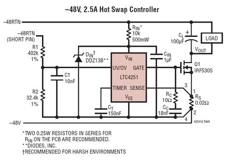
The LTC4251, LTC4251-1, and LTC4251-2 are negative voltage Hot Swap controllers designed to enable the safe insertion and removal of a board from a live backplane. The output current is managed through three stages of current limiting: a timed...
This is a general purpose serial port infrared receiver. With the help of appropriate software, you can control different functions of your PC from a distance. For example, you can control your home cinema settings (volume, play, pause, stop,...
Given favorable radio wave propagation, the shortwave and radio amateur band are filled with SSB (single-sideband) transmissions, which, regardless of the language, will not produce intelligible speech on an AM radio. SSB is transmitted without a carrier wave. To...
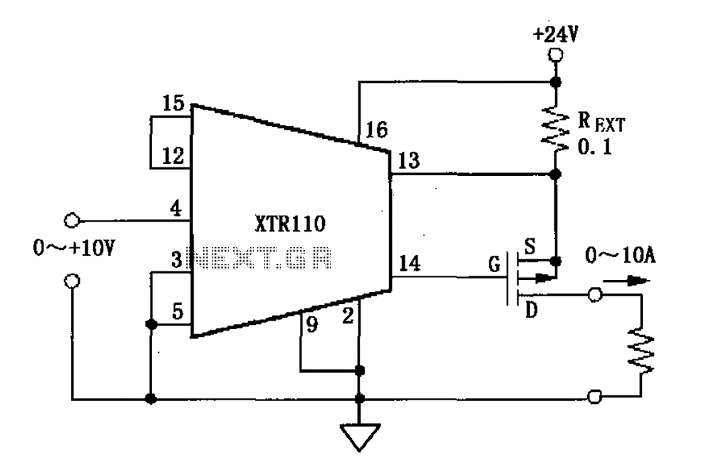
When the output current exceeds 40mA, the XTR110 requires the use of an external resistor (REXT) instead of the internal 50-ohm resistor (R9). REXT should be connected between pin 13 and pin 1. The value of REXT is determined...
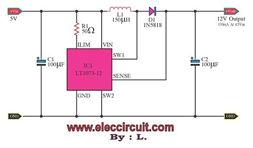
Suppose there is a need to utilize a 5V DC power supply capable of delivering up to 100mA, but only a single AA 1.5V battery is available. To achieve this, a DC to DC converter must be employed. To convert...
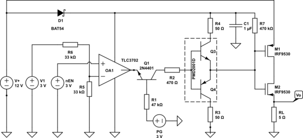
A battery switch-over circuit is being developed, consisting of two parallel lanes as depicted in the circuit diagram. The operational voltage range spans from 3V to 12V. Only one lane should be active at any given time, which is...