
am to fm converter

The circuit employs a regenerative design that leverages the principle of feedback to amplify weak AM signals. The core components typically include a transistor, which serves as the active amplification element, and passive components such as resistors, capacitors, and an inductor, which form the necessary tuning and filtering networks.
The regenerative feedback loop is critical for boosting the signal strength of the incoming AM waves. The transistor is configured in a common emitter or common collector arrangement, depending on the desired gain and impedance characteristics. The tuning capacitor C1, in conjunction with an inductor, creates a resonant LC circuit that selectively enhances signals at specific frequencies, allowing the user to isolate and listen to different AM stations.
For optimal performance, the power supply voltage should be carefully selected to match the specifications of the transistor and other components, ensuring that the circuit operates within its linear range to avoid distortion. A longer wire antenna improves reception by increasing the effective capture area for incoming electromagnetic waves, thus enhancing the overall sensitivity of the circuit.
Once assembled, the circuit should be placed in proximity to the FM radio, which will receive the retransmitted signals. The user can fine-tune the reception by adjusting C1, facilitating the selection of various AM stations. This regenerative circuit design not only provides an innovative solution for listening to AM broadcasts on an FM radio but also serves as an educational project for understanding basic RF principles and circuit design.The above circuit can he used to hear am statons in ur fm radio .It is a regenerative circuit that samples am signals of all frequency and re transmits them in the fm hand [88-108] an even in the TV hand .The capacitor C1 can be varied to receive different am stations thus providing remote tuning facility . Increase the power supply for increased sensitivity .Use an long wire antennae, switch on the circuit and keep it near the fm radio ,now you can hear many am stations.Tune between the stations using c1 🔗 External reference
Related Circuits
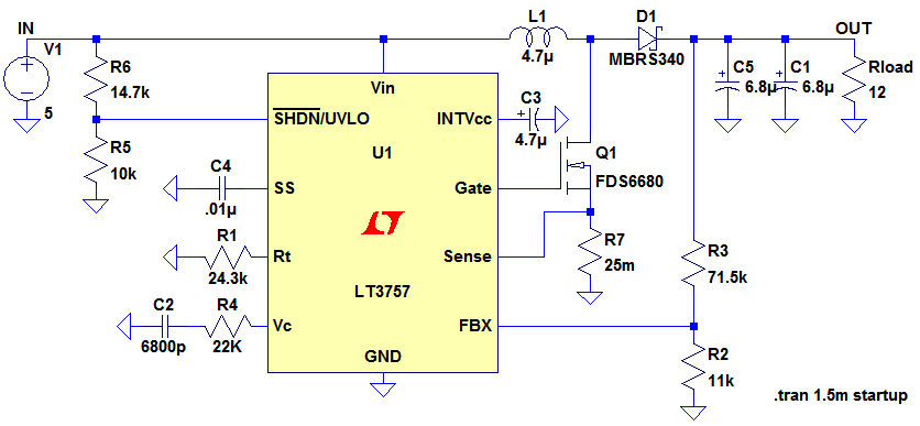
Ignore components C1, C2, R3. The MOSFET, Q1, switches on, creating a short circuit between the right-hand side of the inductor, L1, and ground (0V). A fixed voltage of 3.3V is applied across the inductor, causing its current to...
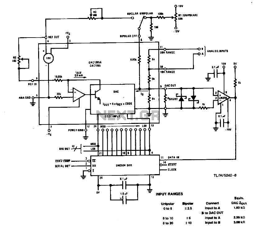
This system performs a complete conversion of 12 bits in both unipolar and bipolar modes. The converter is accurate to ±12-bit LSB with a typical gain temperature coefficient of 10 ppm/°C. In unipolar mode, the system operates within a...
The circuit was designed to create a frequency converter using a crystal oscillator for the conversion of 10 MHz to 1 MHz. It incorporates a 7404 hex inverter. The circuit functions as a frequency divider, utilizing a crystal oscillator to...
The timer is utilized in a conventional setup, with the exception that the timing resistor has been substituted with a current source derived from the operational amplifier DA1 (741). This modification enables the achievement of excellent linearity, exceeding 3%....
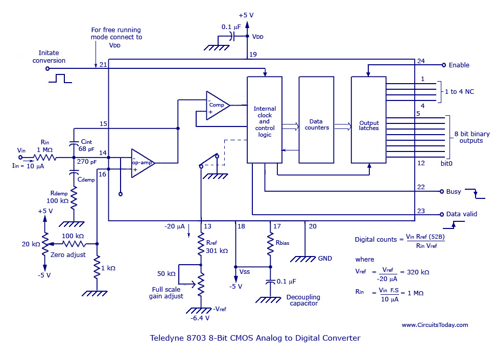
The basic analog to digital (A/D) converter circuit has been previously explained. In addition to this, various types of monolithic analog to digital converters exist, including the integrating A/D, integrating A/D with three-stage outputs, and the tracking A/D with...
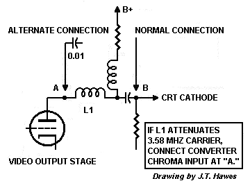
The D 101-2 depends on the television to supply a wide bandwidth video signal. Most black-and-white TVs from 1954 onward contain narrowband intermediate frequency (IF) strips or low-pass filters. A wide passband is a disadvantage because it picks up...