
Amp with Tone Controls & Soft Switching

The described amplifier circuit incorporates tone controls to adjust the frequency response and enhance audio quality. The tone control section typically includes bass, midrange, and treble controls, allowing users to tailor the sound output to their preferences. The implementation of soft switching is a notable feature, achieved through the use of a BD131 transistor. This transistor is configured in an emitter follower arrangement, which provides a high input impedance and low output impedance, ensuring minimal loading on the preceding circuit stages.
In this configuration, the collector of the BD131 transistor is connected to a permanent load, which stabilizes the operation of the transistor and ensures reliable switching performance. The use of soft switching minimizes the audible clicks or pops that can occur during the switching process, leading to a smoother transition between different operating states of the amplifier.
The overall design of the amplifier should also consider power supply decoupling, adequate heat sinking for the transistor, and proper grounding techniques to prevent noise and interference. Additionally, selecting appropriate capacitors and resistors for the tone control circuits will significantly impact the amplifier's performance, particularly in terms of frequency response and signal integrity.
Implementing these design principles will result in a high-quality audio amplifier capable of delivering enhanced sound with user-friendly tone control features.Amp with Tone Controls & Soft Switching. Notes: The soft switching is enabled by a BD131 transistor wired as a switch in emitter follower configuration. The collector is wired to a permanent. 🔗 External reference
Related Circuits
Self-switching power supply. One of the main features of the regulated power supply circuit being presented is that, although a fixed-voltage regulator LM7805 is used in the circuit, its. The self-switching power supply circuit utilizes the LM7805 voltage regulator to...
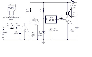
The incoming ring is detected by transistor T1 and the components connected to it. In the absence of a ringing voltage, transistor T1 is in the off state while transistor T2 is forward biased due to resistor R2 being...
The following circuit illustrates a Power Factor Correction (PFC) Switching Power Supply Circuit Diagram. Features include suitability for 1U (1.75-inch) form factor and minimization of input harmonics. The PFC Switching Power Supply Circuit is designed to enhance the efficiency of...

This circuit is capable of delivering approximately 200W of power output, produced by Phillips Semiconductor. It utilizes two PHP1BN11QT devices and operates with an input voltage range of 30 to 45 Volts DC. The described circuit is a high-power switching...
For those who labvoeding built and flow of tension and a leader in providing circuit below was developed. If meter is a moving-coil meter 100?A useful. You have to make yourself a new scale. Also useful is a moving...
The first circuit is a simple preamplifier that illustrates the power arrangements for delivering DC to the amplifier via a coaxial cable. The second circuit includes a minor modification to allow the antenna to remain functional for transmitting. The...