
Amplifier Circuit Output Relay Delay Audio

The circuit operates by utilizing a relay to manage the connection of speakers to an audio amplifier, providing both a delay in activation and immediate disconnection upon power loss. The key components include two capacitors (C1 and C2), two resistors (R1 and R2), and two transistors (Q1 and Q2). The charging and discharging characteristics of C2, in conjunction with the resistors, create the desired delay in speaker activation. The relay serves as a switch that connects or disconnects the speakers based on the control signals from the transistors.
The circuit's design can be optimized for various applications by selecting appropriate values for the capacitors and resistors. For instance, using a larger capacitor for C2 will increase the delay before the speakers are activated, which may be beneficial in applications where a longer delay is necessary to prevent thumping sounds. Conversely, a smaller capacitor will result in a quicker activation, suitable for different scenarios.
In terms of practical implementation, consideration should be given to the specifications of the relay used, ensuring it can handle the load of the speakers without failure. Additionally, the transistors must be chosen based on their voltage and current ratings to ensure reliable operation. Proper thermal management may also be necessary, depending on the power levels involved.
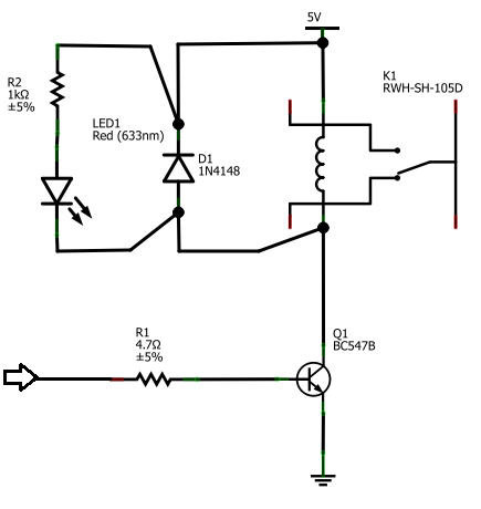
This circuit is versatile and can be adapted for use in various audio applications, including home audio systems, public address systems, and other electronic projects requiring controlled speaker output.This is a simple circuit which I built to one of my audio amplifier projects to control the speaker output relay. The purpose of this circuit is to control the relay which turns on the speaker output relay in the audio amplifier.
The idea of the circuit is wait around 5 seconds ofter the power up until the spakers are switched to the amplfier outp ut to avoid annoying thump sound from the speakers. Another feeature of this circuit is that is disconnects the speaker immdiatly when the power in the amplifier is cut off, so avoinding sometimes nasty sounds when you turn the equipments off. Then power is applied to the power input of the circuit, the positive phase of AC voltage charges C1.
Then C2 starts to charge slowly through R1. When the voltage in C2 rises, the emitter output voltage of Q1 rises tigether with voltage on C2. When the output voltage of Q2 is high enough (typically around 16. 20V) the relay goes to on state and the relay witches connect the speakers to the amplifier output. It takes typically around 5 seconds after power up until the relay starts to condict (at absolute time depends on the size of C2, relay voltage and circuit input voltage). When the power is switched off, C1 will loose it`s energu quite quicly. Also C2 will be charged quite quicly through R2. In less than 0. 5 seconds the speakers are disconnected from the amplifier output. This circuit is not the most accurate and elegant design, but it has worked nicely in my small homebuilt PA amplifier.
This circuit can be also used in many other applications where a turn on delay of few seconds is needed. The delay time can be increased by using bigger C2 and decreased by using a smaller C2 value. Note that the delay is not very accurate because of simplicity of this circuit and large tolerance of typical electrolytic capacitors (can be -20%.
+50% in some capcitors). 🔗 External reference
Related Circuits

Connect a transformer to the motor phase line when the induced voltage is zero volts. In cases of serious imbalance in one, two, or three phases, the transformer’s induced voltage increases rapidly, which leads to an immediate rectification of...
The BC547B transistor has a collector-base voltage (Vcbo) of 50V, a collector-emitter voltage (Vceo) of 45V, and an emitter-base voltage (Vebo) of 6V. In contrast, the BC548 transistor in the original circuit has a Vcbo of 30V, a Vceo...
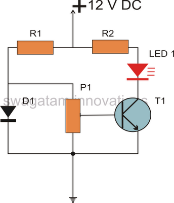
All semiconductors exhibit the tendency to alter their fundamental characteristics in response to changes in ambient temperature. Basic electronic components such as transistors and diodes are particularly susceptible to variations in case temperature. The alteration in their characteristics is...
The Clock Controller was designed to be an exemplary of using 'C' language to control timer0 interrupt, 7-segment LED and keypad scanning. It provides 1-bit sink current driving output, for driving a relay, opto-triac, say. Many projects requiring 7-segment...

A circuit that tailors the low end of particular items such as the bass drum and bass guitar to be used for individual tracks during mixdown, not across the entire mix. With the circuit, I can set the low...
The circuit is based on a single operational amplifier integrated circuit designed to produce a modular preamplifier that operates in Class A configuration. The modular preamplifier circuit utilizes a single operational amplifier (op-amp) integrated circuit, which serves as the primary...