
digital clock circuit

The Clock Controller circuit is designed to effectively manage the operation of a 7-segment LED display and keypad scanning through the use of a microcontroller programmed in 'C'. The primary function of this circuit is to utilize timer0 interrupts for precise timing control, allowing for the display of time or other data on the connected 7-segment display while simultaneously enabling keypad input scanning.
The circuit employs a common anode configuration for the 7-segment LEDs, where the anodes of the LEDs are connected to a positive voltage supply, and the cathodes are controlled by the microcontroller's output pins (P1.0 to P1.7). This configuration allows the microcontroller to sink current when a segment is activated, illuminating the respective segment of the display.
In addition to the LED control, the circuit incorporates a keypad interface, utilizing pins P3.0 to P3.3 to drive the base of four PNP transistors (such as the 2N2907). These transistors act as switches, enabling the microcontroller to manage the current flow through the keypad matrix. When a key is pressed, it completes a circuit that allows the microcontroller to detect the specific key pressed based on the row and column configuration of the keypad.
The design also includes provisions for driving external components such as relays or opto-triacs, providing flexibility for various applications. This is achieved through the 1-bit sink current output, which can effectively control these devices based on the logic output from the microcontroller.
Overall, the Clock Controller circuit serves as a foundational example for projects requiring integration of timekeeping, visual display through 7-segment LEDs, and user input through a keypad, making it a valuable reference for similar electronic designs.The Clock Controller was designed to be an exemplary of using 'C' language to control timer0interrupt, 7-segment LED and keypad scanning. It provides 1-bit sink currentdriving output, for driving a relay, opto-triac, say. Many projects requiring7-segment display and keypad interfacing may get the idea from the Clockcircuit and software.
Figure 1 shows a circuitdiagram of the Clock Controller V1.1. P10-P1.7 drives 7-segment commonanode LED with sink current. P3.0-P3.3 also drives a base pin of 4-PNPtransistor, 2n2907 with sink current. As shown in the figure, the 2nd 2-digitLED that conne 🔗 External reference
Related Circuits
This is a 100 Watt inverter circuit designed with a minimal number of components. The circuit utilizes the CD4047 integrated circuit from Texas Instruments to generate 100 Hz pulses, and it employs four 2N3055 transistors to drive the load....
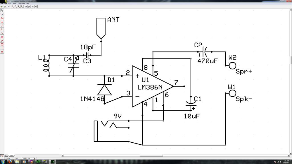
Initially, the individual has limited experience in electronics. They constructed a crystal radio circuit using components salvaged from a non-functional radio, including an LM386N audio amplifier. A crystal radio circuit is a simple radio receiver that operates without the need...
The circuit illustrated relates to a standard industrial UPS (Uninterruptible Power Supply), demonstrating how the batteries assume control during an electrical outage. The Uninterruptible Power Supply (UPS) circuit typically consists of several key components that ensure a reliable power supply...
This LED table or reading lamp circuit can be utilized for various applications, such as a reading lamp for a bed, a desktop or table lamp, a keyboard lamp (to illuminate the keys of a computer keyboard in low...
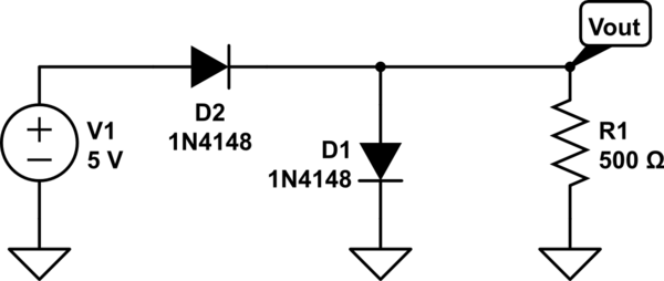
The two diodes will fail. It is advisable to include series resistors for them. If the simulation is successful, the current through the diodes will be excessive. Both diodes do not necessarily need to fail; one may become a...
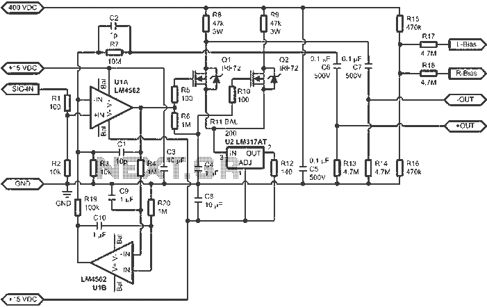
When connected to popular Stax Class 1 electrostatic headphones, the design illustrated in the figures may operate across the full audio bandwidth with a transmission voltage close to 200 Vp-p. Although the resistor divider can be modified to provide...