
Amplifiers connecting Bridge

The circuit described is a bridge amplifier configuration that allows two amplifiers to work together to increase the overall power output to a connected speaker. In this setup, one amplifier operates with a signal in phase (0°) while the other operates with a signal that is 180° out of phase. This phase difference is crucial for achieving the desired doubling of output power.
The circuit includes several components, each serving a specific function. Resistors R1 and R2 are likely used for biasing and setting the input impedance of the amplifiers. Resistors R3 and R4, both valued at 3.9 kOhm, may serve as feedback resistors, helping to stabilize the gain of the amplifiers. The critical resistor in this configuration is R5, which must be calculated based on the supply voltage. The formula provided indicates that R5 should be adjusted to ensure that the voltage across it is 12 V. This resistor plays a vital role in controlling the output and ensuring that the amplifiers are balanced in their operation.
Capacitors C1, C2, and C3, each rated at 4.7 µF, are likely employed for coupling and decoupling purposes. They help to filter out unwanted noise and stabilize the power supply, ensuring that the amplifiers operate efficiently and without distortion.
The transistor T1, identified as a BC 547B, functions as a switching or amplification component within the circuit. It may be used to control the signal flow between the amplifiers, ensuring that the correct phase relationship is maintained.
It is essential to ensure that both amplifiers used in this configuration are identical in specifications to achieve optimal performance. Any discrepancies in their characteristics could lead to inefficiencies or potential damage to the amplifiers or connected speaker. The overall design must consider the power supply requirements, ensuring that the dual power amplifiers are adequately powered for reliable operation.
In summary, this circuit effectively combines two amplifiers in a bridge configuration, utilizing careful component selection and phase management to enhance audio output power while maintaining signal integrity.This is a circuit that ensures that you can connect two amplifiers together so you get more power. When called in bridge linking two amplifiers plus you can link the outputs of the amplifiers to the speaker (see block diagram). One of the amplifiers, or with a signal in opposite phase are controlled, because otherwise you do not get double output.
For anti-phase signal makes this circuit. One has to be ensured that the two amplifiers are the same. One amplifier is then controlled by the signal output from the 0 °, and the other is driven by the 180 ° output. R5 should be adapted to supply voltage. The tension left of R5 should be 12 V.. The resistance has the following formula to calculate: R = (R - 12) / 0.0015. Here R is the resistance of R5 and R5 V power supply right. When building the power you need to take into account that of course the dual power amplifiers two questions.
Parts List: R1 = 330 kOhm R2 = 120 kOhm R3, R4 = 3.9 kOhm R5 = see text C1-C3 = 4.7 uF T1 = BC 547B 🔗 External reference
Related Circuits

The Wien-bridge oscillator is a distinctive circuit that produces an oscillatory output signal without requiring a sinusoidal input source. Instead, it utilizes capacitors with initial voltages to generate the output. This circuit can be particularly beneficial when connected to...
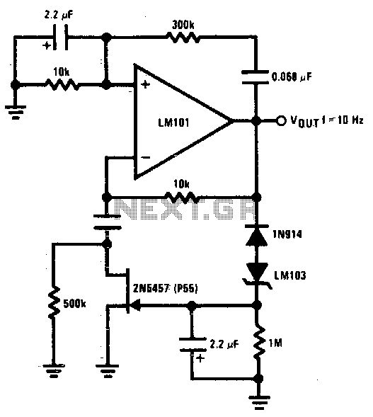
The 2N5457 JFET is utilized as a voltage variable resistor within the amplifier feedback loop, resulting in a low distortion, constant amplitude sine wave and optimizing the amplifier loop gain. The LM103 zener diode serves as the voltage reference...
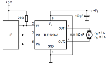
The schematic below illustrates the TLE5206-2 5A H-Bridge circuit for DC motor applications. This device features an integrated power H-bridge with DMOS output stages designed specifically for driving DC motors, as indicated in the datasheet. The TLE5206-2 circuit application...
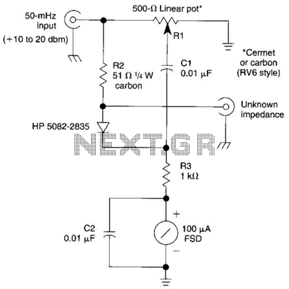
The bridge shown was used for measurements on 50-MHz amateur radio antennas. Rl is a miniature 500 linear potentiometer. The unknown impedance is compared to R2, a 51-ohm resistor. An external signal source is required. The described bridge circuit is...
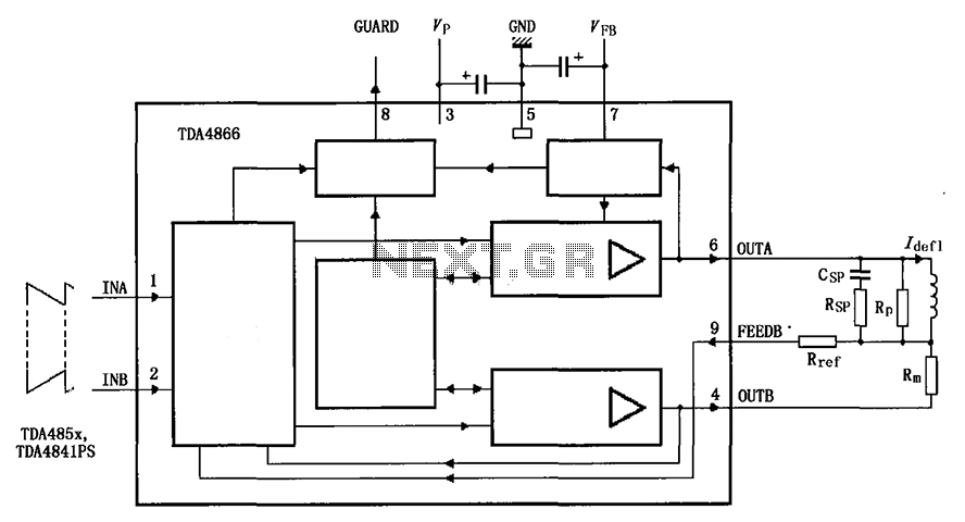
The TDA4866 is a 90-color power amplifier designed for vertical deflection systems, operating at a frequency range of 50 to 160 Hz. The CRMM circuit is implemented to ensure a high current drive input. The amplifier features a dual...
For a project such as a robot or car, an electronic circuit is required, controlled by a control circuit. This control circuit outputs signals to manage an H-Bridge. The circuit includes a Hex Bug design, where the control circuit...