
An SCR Based Burglar Alarm

The SCR-based burglar alarm circuit operates on the principle of using silicon-controlled rectifiers (SCRs) to manage the flow of current in response to input from various sensors. The circuit typically includes a power supply, SCR, resistors, capacitors, and input devices. The power supply provides the necessary voltage and current to the circuit, while the SCR acts as a switch that can be turned on or off based on the input from the sensors.
When the system is armed, the entry and exit delays are managed by timing circuits that use RC (resistor-capacitor) networks. The values of resistors R2, R7, and R11 influence the timing intervals, allowing customization based on user needs. The input devices, such as magnetic reed switches or PIR sensors, are connected to the circuit in a normally-closed configuration, ensuring that the circuit remains closed until a breach is detected.
If a breach occurs, the SCR is triggered, allowing current to flow to the alarm output, which can be either a buzzer or a siren. The circuit is designed to provide an initial buzzer sound to alert the user of the breach, followed by a siren activation if the alarm is not deactivated within the specified time. The timed cut-off feature ensures that the alarm does not remain active indefinitely, reducing the risk of nuisance alarms.
The modular design of the alarm system allows for expansion by adding more zones, which can be configured to respond to different types of input devices. This flexibility is particularly beneficial for larger premises, where multiple entry points need monitoring. Each zone can be independently configured to have its own delay settings, enhancing the overall security of the system.
For optimal performance, it is essential to ensure that the components used in the circuit are of high quality and compatible with the intended load. The use of a heatsink for the SCR is crucial when higher currents are expected, as it helps dissipate heat and prevent damage to the device. Additionally, careful consideration should be given to the relay contacts, which may need upgrading to handle the increased load if a conventional bell or other high-current device is used.
Overall, this SCR-based burglar alarm circuit provides a reliable and customizable solution for security needs, with features designed to minimize false alarms while ensuring effective response to unauthorized access.This is a simple SCR based burglar alarm circuit. Its features include automatic Exit and Entry delays - together with a timed Bell cut-off and Reset. It`s designed to be used with the usual types of normally-closed input devices such as - magnetic-reed contacts - micro switches - foil tape - and PIRs. The basic alarm has a single zone with "Exit/ Entry" delays. This will be adequate in many situations. However - larger buildings are better divided into zones. The modular design means that you can Add Any Number Of Zones to the system. These "Instant" zones may be triggered by normally-open as well as normally-closed input devices. It`s easy to use. When you switch on the alarm - you have about 30 seconds to leave the building. When you return and open the door - the Buzzer will sound. You have about 30 seconds to switch off the alarm. If you fail to do so - the Siren will sound. After about 10 minutes - the alarm will attempt to reset itself. If the trigger circuit has been restored - the attempt will be successful. But - if the loop is still open - the attempt will fail - and the alarm will re-activate. Of course - you can turn the Siren off at any time by switching off the alarm. A conventional bell uses up to about 400ma. An electronic siren generally uses less. If you intend to draw a heavier current from either the Buzzer or Siren terminals - the SCR in question will need to be bolted to a metal heatsink - and the relay contacts may need upgrading. Because of manufacturing tolerances - the precise length of any delay depends on the characteristics of the actual components you`ve used in your circuit.
But - to some degree - by altering the values of R2, R7 & R11 you can adjust the Exit, Entry and Reset times to suit your requirements. Increasing the values increases the time - and vice-versa. 🔗 External reference
Related Circuits

When the protective circuit is interrupted (opened), the alarm sounds. To set the circuit, adjust R2 (with the protective circuit open) for 1 V across R1. The described circuit functions as a protective alarm system that activates when the integrity...
The primary objective of this design was to address a minor flaw in the widely used Fridge Door Alarm circuit, which has been available on this website since 1999 and has been constructed by numerous hobbyists. This circuit ceases...
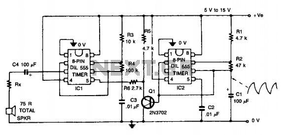
This circuit simulates the sound of an American police siren. IC2 is configured as a low-frequency astable multivibrator, producing a cycling period of approximately 6 seconds. The slowly varying ramp waveform generated on capacitor C1 is fed to the...
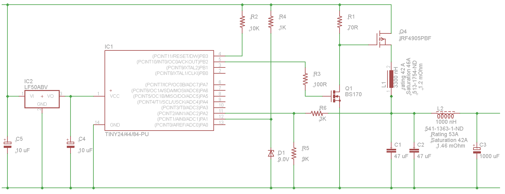
The microcontroller will not be able to drive the gate of Q1 effectively, as GPIO pins typically can only source a few milliamps, resulting in slow turn-on and turn-off times. This limitation will affect the performance of the high-side...
The following circuit illustrates how to build a variable DC power supply circuit. This circuit is based on the 7805 IC. Features: other output is ... The variable DC power supply circuit utilizing the 7805 integrated circuit (IC) is designed...
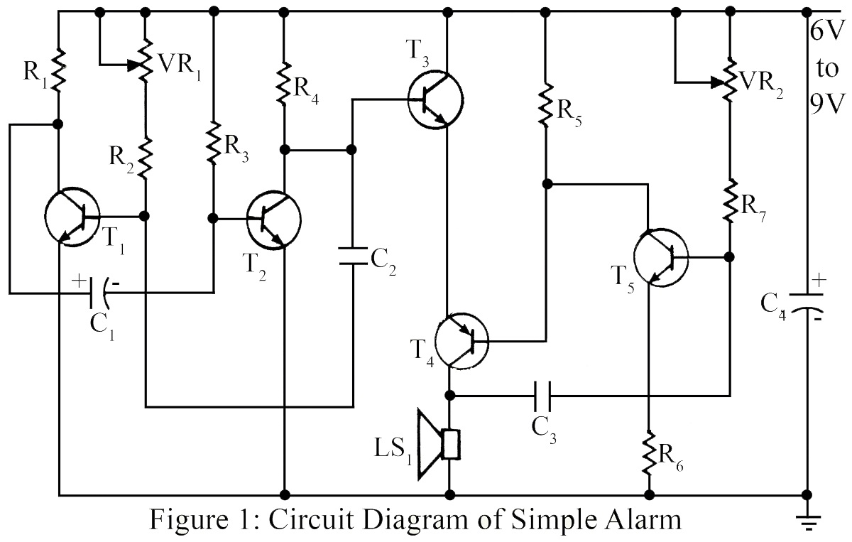
The simple circuit generates an audible alarm notification, functioning as a burglar alarm utilizing five transistors. This circuit operates as a basic burglar alarm system designed to emit an audible sound when triggered. The core component of the circuit is...