
How To Build The Variable DC Power Supply Circuit Based On The 7805 IC

The variable DC power supply circuit utilizing the 7805 integrated circuit (IC) is designed to provide a stable output voltage while allowing for adjustable voltage levels based on the user's requirements. The 7805 IC is a popular voltage regulator that can output a fixed 5V, but with the addition of certain components, it can be modified to deliver a variable output.
The circuit typically includes a transformer, a bridge rectifier, filter capacitors, and the 7805 voltage regulator. The transformer steps down the AC voltage from the mains supply to a lower AC voltage suitable for regulation. The bridge rectifier converts the AC voltage to pulsating DC, which is then smoothed out by filter capacitors to reduce ripple and provide a more stable DC voltage.
To achieve variable output, a potentiometer can be incorporated into the circuit. This potentiometer adjusts the feedback voltage to the 7805, allowing the output voltage to vary. Additionally, capacitors may be added at the output to stabilize the voltage and improve transient response.
It is important to ensure that the input voltage to the 7805 is within the specified range, typically between 7V to 35V, to prevent damage to the IC and ensure proper regulation. Proper heat sinking may also be necessary, as the 7805 can generate heat during operation, especially under high load conditions.
Overall, this variable DC power supply circuit is beneficial for various applications requiring a stable and adjustable voltage source, making it a versatile tool for electronic projects and experiments.The following circuit shows about How To Build The Variable DC Power Supply Circuit. This circuit based on the 7805 IC. Features: other output is .. 🔗 External reference
Related Circuits
The W7800 is a positive integrated voltage regulator, while the F007 consists of an operational amplifier used in a power supply tracking application circuit. Some configurations utilize both positive and negative power supplies, with a negative supply necessary to...
This is a game timer circuit diagram. When the game timer is reset, two actions must occur: the 4017 counter must return to zero, and the 4060... The game timer circuit utilizes the 4017 decade counter and the 4060 binary...

This method can be illustrated using an uncommon semiconductor power flip-flop. A flip-flop is a toggling circuit with two stable states (bistable multivibrator) that retains its output state without an input pulse. Triacs can be used to implement flip-flops...
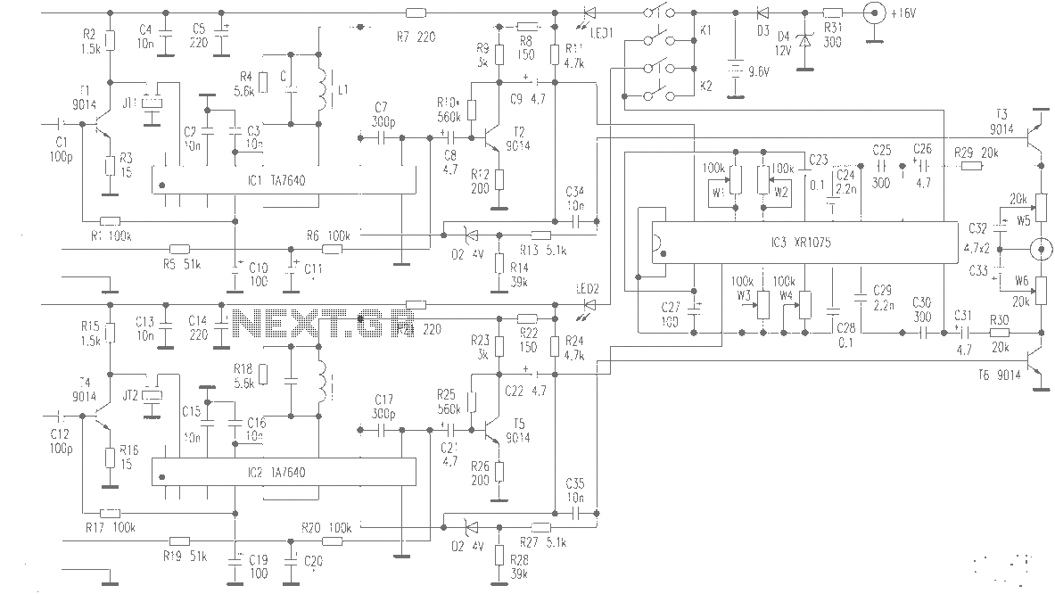
The production of high-quality wireless microphones is a common aspiration among enthusiasts, but achieving a high-performance receiver is challenging. This project explores the use of salvaged FM radio cassette players to enhance an XR1075 audio processor, leading to the...
The following circuit diagram represents a battery charger designed for a 12V car battery. This circuit includes overcharging protection, which automatically disconnects the charging circuit. Unlike typical battery chargers that continuously supply a few amperes to the battery while...
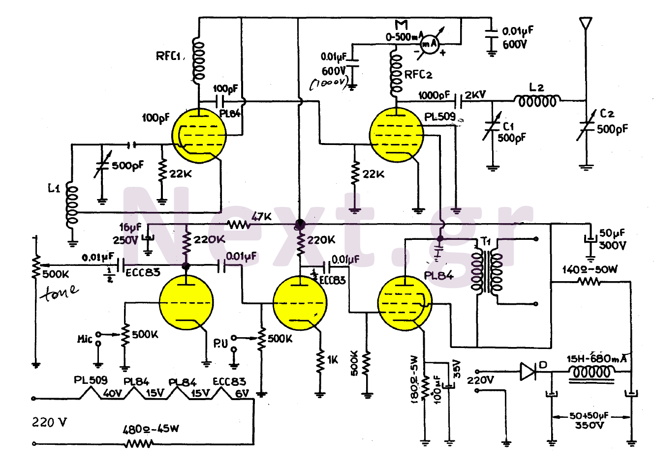
The simplicity of this transmitter, combined with its high performance, makes it particularly interesting. It has an output power of approximately 30 W, and under normal conditions, with the appropriate antenna and handling, it can achieve a range of...