
Analog Mains Frequency Meter


This circuit is designed to measure the frequency of an emergency generator by comparing it to the stable mains frequency. The primary components include a 25K multiturn trimmer for calibration, a series of resistors, and capacitors that have been carefully selected for their stability and precision. The circuit requires that certain resistors and capacitors be used in specific configurations to achieve the desired frequency response. For instance, the value of 3777 is derived from a combination of a 3900-ohm resistor in parallel with a 120K-ohm resistor, while 4020 is created using a 3900-ohm resistor in series with a 120-ohm resistor.
Capacitors must be rated for direct connection to the mains, and their voltage ratings should exceed the maximum expected voltage to ensure safety. The circuit also includes a 100µF capacitor, which could be reverse biased under certain conditions, but this capacitor is generously rated to handle such scenarios. The design stipulates that resistors with a low temperature coefficient be used to maintain accuracy during operation, as temperature fluctuations can affect the zero setting and filter response.
The operational procedure involves connecting the circuit to the mains power supply first, allowing a warm-up period of approximately 4-5 minutes for the resistors to stabilize, followed by calibration using the trimmer. After calibration, the circuit can be connected to the generator. It is important to note that variations in mains voltage will not affect the zero setting but will influence the sensitivity of the meter. For example, a frequency reading may shift slightly with changes in voltage supply.
The circuit can accommodate a frequency range of +/- 2 Hz for standard applications; however, adjustments can be made to increase this range to +/- 3.5 Hz by changing the 2.2K-ohm resistor to a 12K-ohm resistor, which is particularly useful for petrol-driven generators.
Safety precautions are critical, as this circuit is connected directly to the mains. It is recommended that the entire assembly be enclosed in a protective box to prevent accidental contact with live components. Proper care must be exercised during calibration to avoid electrical hazards. For users operating in regions with 110 VAC, 60 Hz mains, an alternative circuit configuration may be utilized, with specific capacitor values calculated for compatibility.Mains frequency is pretty stable and it is unlikely that you have to measure it but if you have an emergency generator you might find this circuit useful as it will give an indication whether the generator is running too fast or too slow. Actually you can use the mains frequency to calibrate it by adjusting the 25K multiturn trimmer until it reads 0.
The odd looking components values are easily obtained using standard values: 3777 is 3900 in parallel with 120K?, 4020 is 3900 and 120 in series, 570nF is 470nF with 100nF in parallel and 400nF is 4 x 100nF capacitors in parallel. Components should be chosen for their stability and precision. 1% tolerance would be ideal but 5% is acceptable so long as you measure them with a good meter. Capacitors should be properly rated for direct connection to the mains and resistors should have a low temperature coefficient as it will adversely affect the zero setting and change the filters response. The 100?F capacitor could be occasionally reverse biased with a voltage of 0.1-0.2 V. There is no problem for the capacitor which is generously rated. Operation is quite simple: connect it first to the mains, wait about 4-5 minutes until all resistors reach their working temperature, calibrate, and then connect to the generator.
Variation in the mains voltage will not change the zero setting but will make the meter more or less sensitive: for example, a reading of 51 Hz will show as 51.1 with a 10% supply voltage increase. Full scale deflection is around +/- 2 Hz. If you wish to accommodate a wider range of +/- 3.5 Hz, typical for a petrol driven generator, you have to change the 2.2K?
resistor to 12K?. WARNING! This circuit is directly connected to the mains and should be assembled in a box which will avoid access to any of its part and care must be exercised when calibrating the unit. If you live in the States or you have a 110 VAC, 60 Hz mains, you may try the second circuit: the reported values are calculated values, I did not actually test the unit.
The odd capacitors values are easily obtained with the combination of standard values: 0.94 is 2 x 0.47 in parallel, 1.056 is 1?F + 56nF in parallel and 1.1 is 1 + 0.1?F. 🔗 External reference
Related Circuits
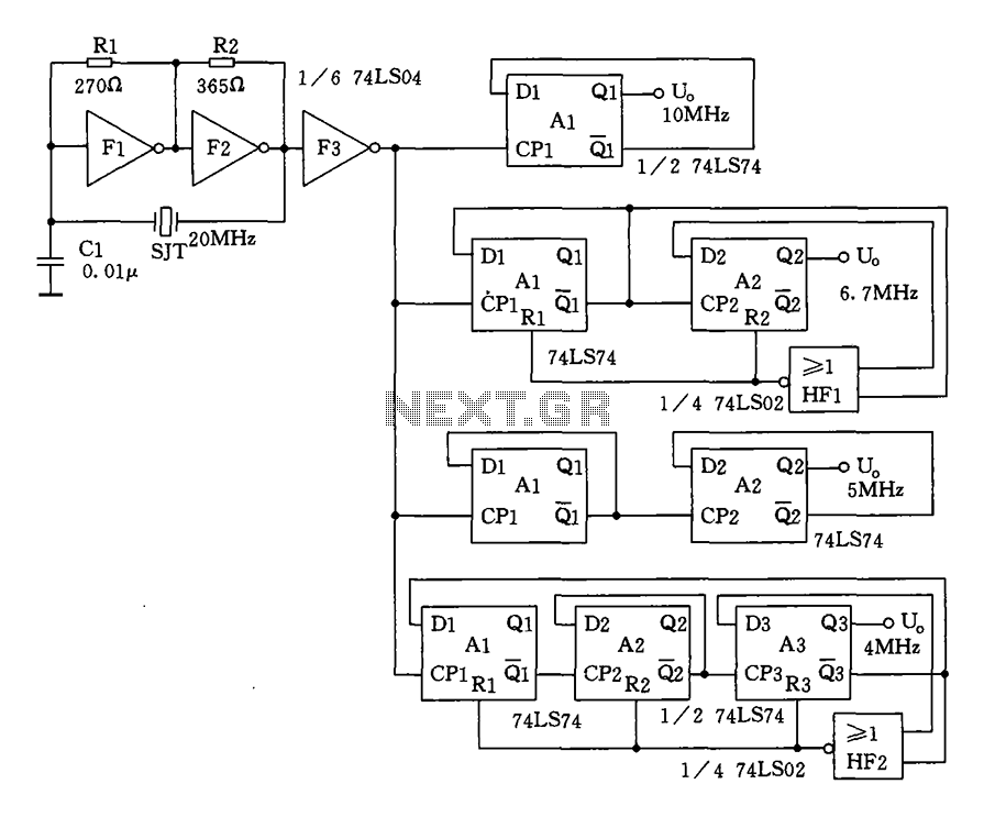
Crystal oscillator and frequency divider (74LS04) circuit diagram. The circuit diagram for a crystal oscillator combined with a frequency divider utilizing the 74LS04 integrated circuit is designed to generate a stable clock signal. The crystal oscillator component typically consists of...
To ensure the circuit functions properly, it is crucial to correctly configure the fuse bits within the AVR microcontroller. These fuse bits can be set using the programmer employed to upload the software. For those interested in the technical...
As equipment becomes increasingly compact, designers are often required to reduce the size of displays. However, this can compromise the usefulness of the display. Many individuals find it challenging to read small displays, which can be particularly frustrating. In...

This is a CMOS-compatible (and ideally also TTL-compatible) input that includes over-voltage and under-voltage protection. Schmitt triggers are utilized to accommodate inputs with long transition times. It has been verified to function at frequencies up to 30 MHz. The described...
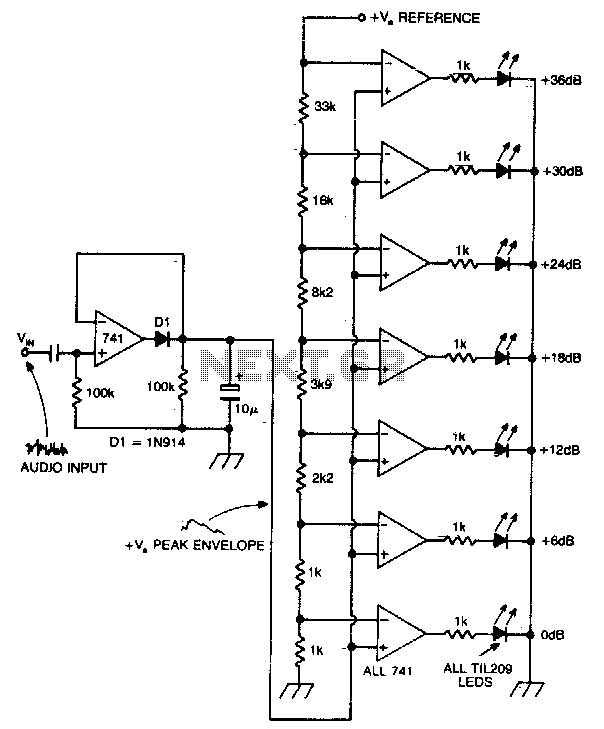
A vertical column of LEDs is configured so that as the audio signal level rises, an increasing number of LEDs illuminate. The LEDs are arranged in increments of 6 dB. The circuit features a fast response time and a...
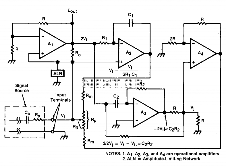
An oscillator/amplifier is resistively tunable over a wide frequency range. Feedback circuits containing operational amplifiers, resistors, and capacitors synthesize the electrical effects of inductance and capacitance in parallel between the input terminals. The synthetic inductance and capacitance, and therefore...