
Analog Tachometer Readout

The analog display circuit is designed to visualize engine RPM through a series of illuminated LEDs, providing real-time feedback to the operator. The frequency-to-voltage converter (IC12) takes the input frequency from the engine's tachometer signal and converts it into a proportional voltage. This conversion is crucial as it allows for a straightforward interpretation of engine speed in a visual format.
The output voltage from IC12 is fed into the bar-graph segment drivers, IC10 and IC11, which manage the illumination of the LED segments. These drivers are responsible for controlling the brightness and activation of the LEDs based on the voltage levels provided by IC12. Each segment corresponds to a specific range of RPM, allowing the operator to easily gauge engine performance.
R34 serves as the calibration adjustment resistor, enabling fine-tuning of the system to ensure accurate LED activation at the specified RPM thresholds. By adjusting R34, the system can be calibrated to light the first LED at an engine RPM of 5,000 to 7,000, marking the critical redline value. This feature is essential for performance monitoring, as it helps prevent engine over-revving and potential damage.
Overall, this analog display circuit provides a reliable means of monitoring engine RPM, utilizing a combination of frequency-to-voltage conversion and LED visualization to enhance user experience and safety.The analog display consists of a frequency/voltage converter (IC12) and bar-graph segment drivers IC10 and IC11. R34 is the calibration adjustment and is set so that an engine rpm of 5 000 to 7000 rpm lights the first LED (redline value)
🔗 External reference
Related Circuits
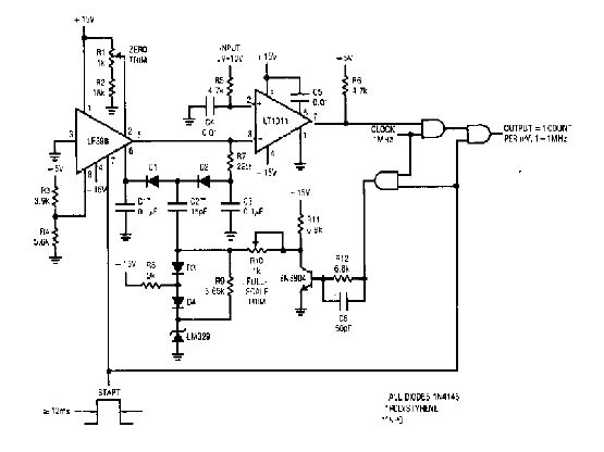
The simple 4-digit converter circuit has an output count of 1, designed to operate within a frequency range of f-IMHz to 10.000. All diodes used in the circuit are IN4146, and the capacitors are made of `POLYSTYRENE` NPO. The...
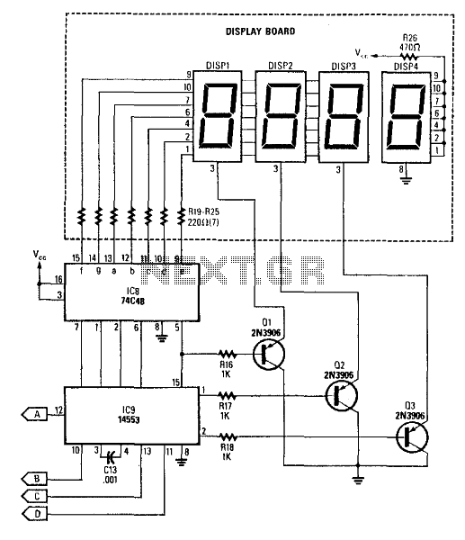
This circuit produces a readout for the digital tachometer circuit. IC9 is a 3-digit LED display driver, counter, and latch. IC8 drives the common-cathode LEDs, which are enabled by Q1, Q2, and Q3. See page 268, Fig. 46-5 for...
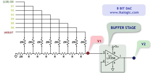
This article introduces a simple solution for beginners and intermediate readers to build a digital-to-analog converter (DAC) using an R/2R resistor network. It also addresses common challenges faced by beginners while constructing their own DACs and offers straightforward solutions....
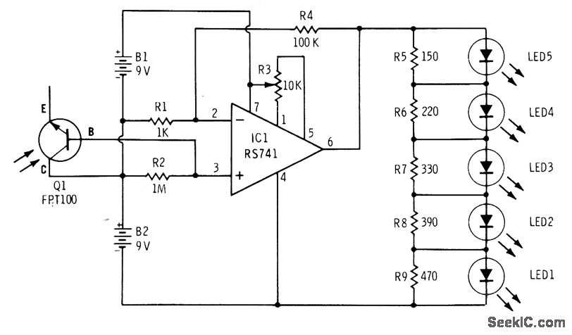
The phototransistor Q1 (Radio Shack 276-130) activates a voltage change across resistor R2, which is then amplified by an operational amplifier (op-amp). The output from the op-amp drives an array of five LEDs, creating a bar graph voltage indicator....
The time constant of R1C1 determines the low cutoff frequency, while the time constant of R2C2 determines the high cutoff frequency. The pass-band gain, Avpass = R2/R1. For a high-pass filter, Za must be capacitors and Zb resistors. By...
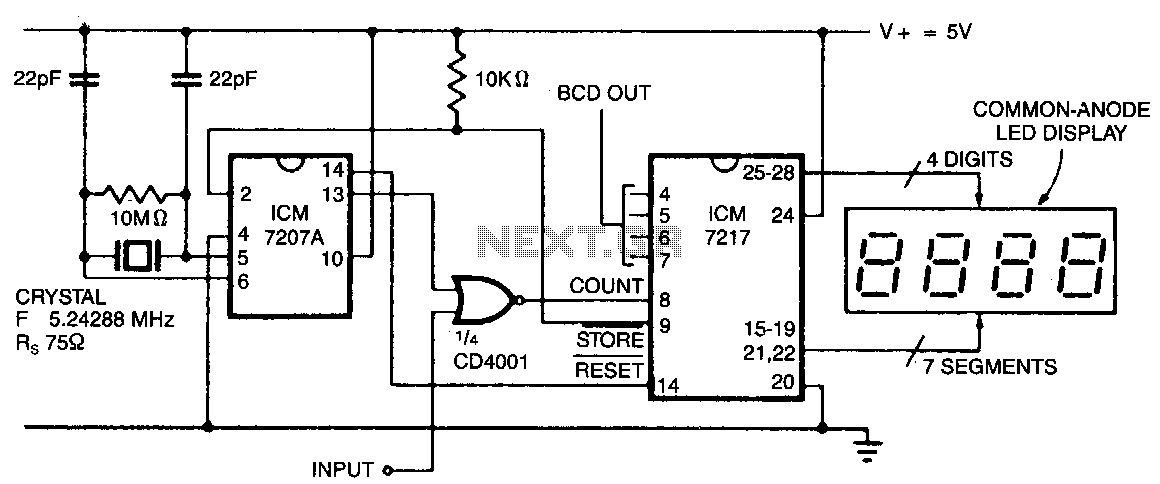
In this configuration, the display shows hertz directly. When pin 11 of the ICM7027 A is connected to V00, the gating time is set to 0.1 seconds, allowing the display to represent tens of hertz as the least significant...