
Analogue Pulse Counter Schematic

The circuit designed for the welding machine application serves to manage the welding head's operation by providing an analogue over-run counter, which is essential for ensuring the proper overlap of weld beads on cylindrical components. The primary operational components include a cup-and-bucket charge pump, which facilitates the accumulation and transfer of electrical charge in a controlled manner.
The cup-and-bucket mechanism consists of two capacitors: the smaller capacitor (C1), referred to as the "cup," and the larger capacitor (the "bucket"), which is typically a 100nF capacitor connected to the gate of a BF244 JFET. The input to the circuit is a pulse train, which can be a square wave or similar signal, that triggers the counting process.
Upon receiving a high signal at the Start input, transistor Tr1 is activated, which in turn deactivates Tr2, allowing the collector of Tr5 to float upwards. As the count input receives a pulse, C1 discharges through a diode into a preset wiper, incrementing the voltage stored in the bucket. When the count input signal returns to a low level, C1 charges through the emitter of transistor Tr3. The flow of current from the collector of Tr3 causes a slight drop in voltage at the gate of Tr4, which ceases its conduction. This action allows current to flow through a 3.3MΩ capacitor, subsequently turning on Tr5, which raises the collector voltage and restores the gate voltage of the bucket capacitor.
The unique design of this circuit allows for a variable ratio between the cup and bucket capacitors, enabling flexibility in how the circuit responds to input signals. For example, if the cup is 100pF and the input voltage swing is 10V, then a 10mV change occurs at the collector of Tr5 for every input pulse. This ratio can be adjusted to suit specific application needs, ensuring that the circuit can accommodate various input frequencies and amplitudes.
Additionally, the circuit's design considerations include the use of low-leakage components, particularly the JFET, which helps maintain the integrity of the stored charge in the bucket. An alternative configuration using an NPN transistor can also be employed, simplifying the design by eliminating the need for a preset adjustment.
Overall, this analogue over-run counter circuit not only fulfills a specific requirement for welding machines but also comprises versatile blocks that could be adapted for other electronic applications, such as staircase generators, analogue counters, and comparators with controlled hysteresis.It was designed for an application in a welding machine: there are lots of bits of machinery which are cylindrical in shape and which are subjected to heavy surface wear. For instance ore crushers, and the idler and roller wheels off track laying vehicles, much used in earth moving.
These wear quickly, so it makes sound economical sense to re-surface the component with a hard metal. This is typically done by a welding process, using a hard facing alloy. As the item is rotated at a steady rate, the weld head oscillates fron side to side, laying down weld in a zig-zag or square wave pattern. At the end of a complete turn, the weld head is moved sideways by a distance more of less equal to the oscillation width, allowing for some overlap.
On the last turn, the head must not be moved sideways but the weld must be 'over-run' a little to overlap into the new surface. Some machines are designed to handle components with a wide range of diameters. These machines used a stepper motor for the rotation, because they give such a wide range of speeds. This circuit is an analogue over-run counter for such a stepper rotator! As such an application, it is an uncommon requirement! But the circuit may be of general interest. This circuit is actually two main blocks, each of which may be useful in other ways. The first block, to the left, up to and including Tr5, is a cup-and-bucket charge pump. In case you don't know the term, it refers to a small capacitor (the cup - C1) dumping its charge into a larger one (the bucket).
At a particular level, the bucket overflows and triggers something else. It's a sort of analogue divider if you will! The bucket is the 100n capacitor connected to the gate of the BF244 (J-FET). Input should be a pulse train (squarewave or similar) of repeatable amplitude fed into the count input. To start the circuit, Start input must go high enough to turn on Tr1 which turns off Tr2. The collector of Tr5 is now free to float upwards. Each time the count input goes up, C1 discharges through the diode into the wiper of the preset. When count goes low, C1 charges through Tr3's emitter. But Tr3's emitter current must flow in from the collector so the voltage on Tr4's gate falls slightly.
Tr4 therefore stops conducting, current flows through the 3M3 capacitor and turns on Tr5 causing Tr5's collector to rise enough to restore the gate voltage. The cup charge has flown into the bucket, changing its voltage. Now if the cup is, say 100pf and the input voltage swing (into 'count') is 10v, then the change on Tr5's collector will be 10mV.
You can adjust the values to suit. Putting it another way, the ratio of bucket to cup is 1000:1, then we need 1000 10v input pulses to swing the output by 10 volts You can chose the cup and bucket sizes to suit yourself. Remember that the bucket must be low leakage - which is why I've used a JFET for the input, but the circuit works also with an NPN transistor for input.
With a JFET, the 'pinch off' voltage (at which point the circuit operates) is variable, so we feed a preset to adjust the circuit's operating point. With an NPN transistor for input you can remove the preset and attached pieces and connect Tr3's base to +ve line.
The transistor will slightly leak away the charge in the bucket. The circuit contains elements: Staircase generator Analogue 'counter' Comparator with controlled hysteresis Cup and bucket charge pump 🔗 External reference
Related Circuits
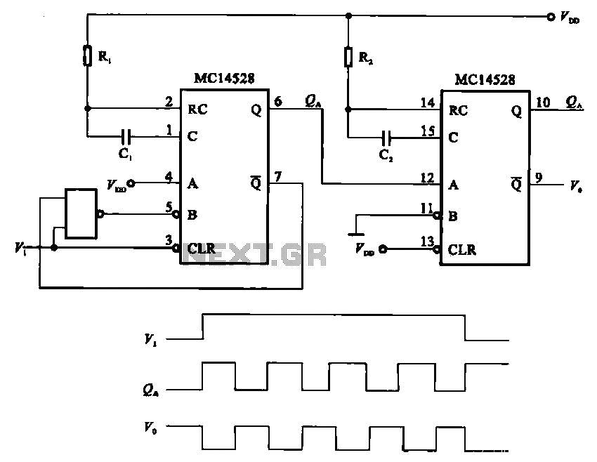
The pulse generating circuit monitors signals using monostable flip-flops. It generates a single-shot output signal based on the input pulse signal. A key signal from the monostable flip-flops is represented in a formula, with the input (V1) and output...
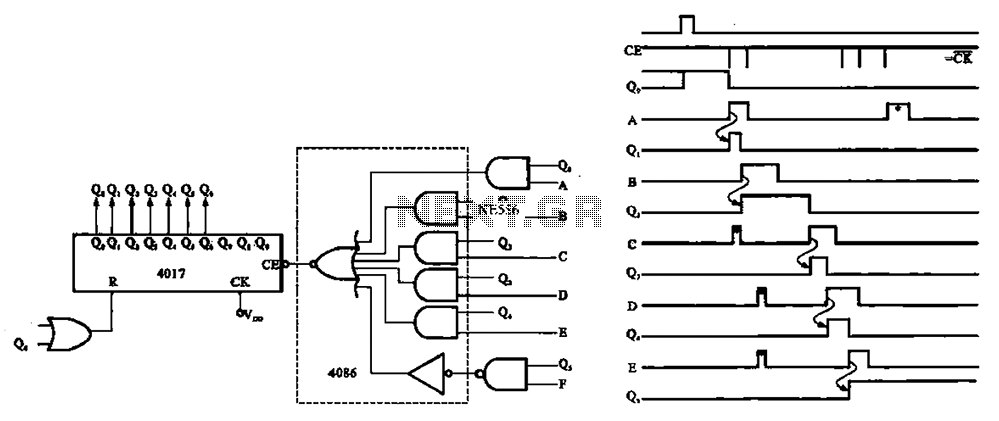
An asynchronous counter is illustrated in this circuit. It operates without a clock synchronization signal, making it suitable for use in a random counter or as an independent unit circuit. An asynchronous counter, also known as a ripple counter, is...
Digital counters have various applications in electronic circuits. In digital electronics, counters are utilized in different situations. This article presents the concept of a ring counter circuit, which functions as a register counter. An animation and simulation video of...
The circuit receives its input from the zero-crossing detector, which generates a 0-to-1-to-0 pulse to set the R-S flip-flop and activate the ramp circuit (A to Ramp) to initiate the timing ramp ascent. The described circuit operates by utilizing a...
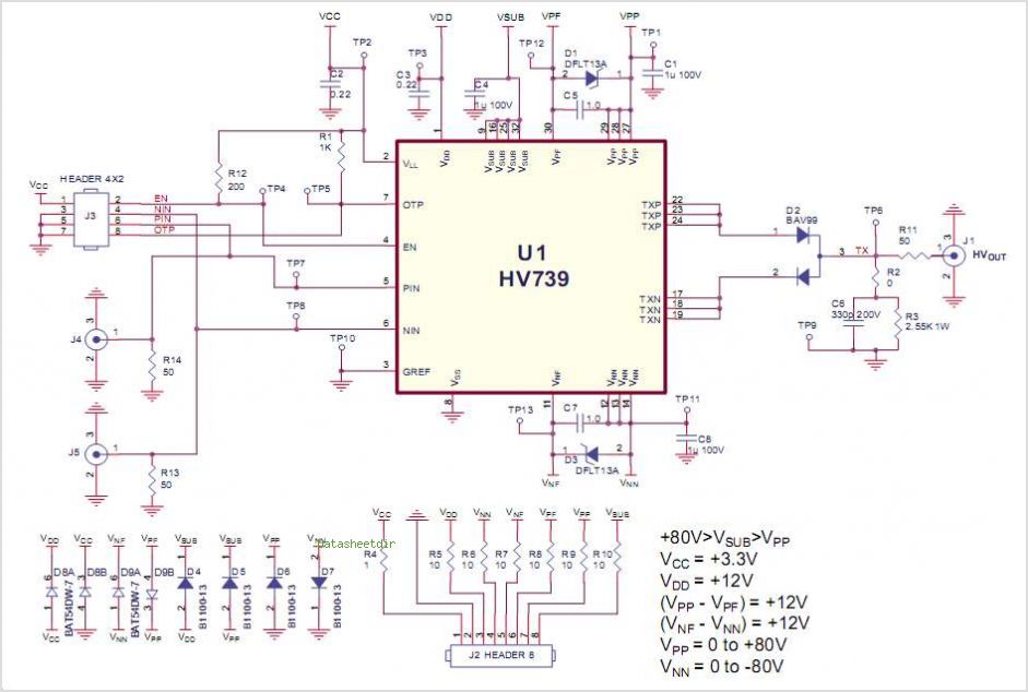
This demo board data sheet explains how to utilize the HV758DB1 to produce a fundamental high voltage pulse waveform for use as an ultrasound transmitting pulser. The HV758 circuit employs a DC coupling method in all level translators, eliminating...
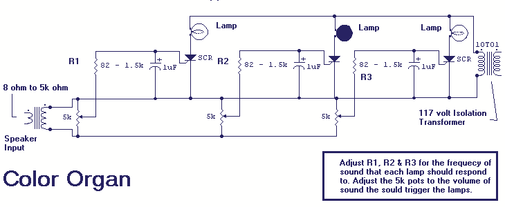
The basic idea of the project is to make different colored bulbs light at different frequencies of music. The circuit connects to the speaker outputs of your stereo or to the back of your speaker. The music passes through...