
Sine wave converter circuit

The circuit utilizes a 74HC04 hex inverter, which is integral for generating the oscillation frequency. The inverter's output can be configured to produce a square wave signal, which is a fundamental aspect of many signal generation applications. The resistor R is crucial in setting the frequency of oscillation; by adjusting its value, the output frequency can be finely tuned to meet the requirements of various calibration tasks.
The supply voltage (Tl) is dynamically influenced by the amplitude of the output signal, allowing for a responsive design that adapts to varying signal levels. This characteristic is particularly useful in applications where sensor signals may fluctuate, ensuring consistent performance across a range of operating conditions.
The switch plays a pivotal role in shaping the output waveform. By toggling the switch, the output can be transformed from a varying voltage level into a square wave signal. This square wave is then subjected to low-pass filtering, which effectively attenuates higher frequency components that are not desired in the final output. The design of the low-pass filter is critical; it typically consists of passive components such as resistors and capacitors, which work together to smooth out the square wave into a cleaner sine wave.
The performance of the low-pass filter directly affects the fidelity of the output waveform. The cutoff frequency of the filter must be carefully selected to balance between adequate signal smoothing and maintaining the integrity of the desired frequency component. Additionally, depending on the application, a series of filters may be utilized to achieve the desired level of signal purity and distortion minimization.
In summary, this circuit design is versatile and can be adapted for various calibration and sensing applications, with careful consideration given to component selection and configuration to optimize performance.The circuit can be used as the signal source of calibration level meter or sensor-driven differential transformer. Circuit oscillation frequency is determined by the 74HCO4, and it is transferred lkHz by R. The supply voltage of Tl changes with the amplitude output. The switch turns the output voltage into square wave, then it will get sine wave b y filtering the high frequency by low-pass filter. Waveform distortion depends on the performance of the filter, and the series of filter is used according to the need. 🔗 External reference
Related Circuits
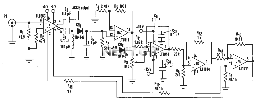
A simple IF AGC signal with a wide dynamic range and excellent linearity characteristics may be composed of two chips: the TL026C T1 voltage control amplifier IC and the LT1014 (or any other similar basic quad op amp device). The...
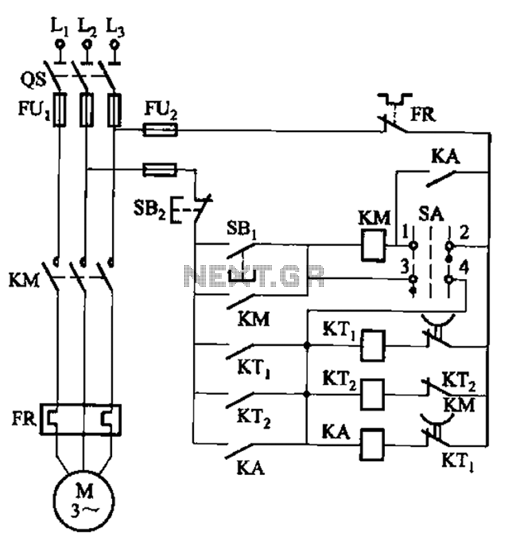
The circuit illustrated in Figure 3-78 utilizes two relays for automatic control, featuring a more complex line structure. This configuration allows for intermittent motor operation. Additionally, it can operate continuously when switch SA is positioned to the right. The circuit...
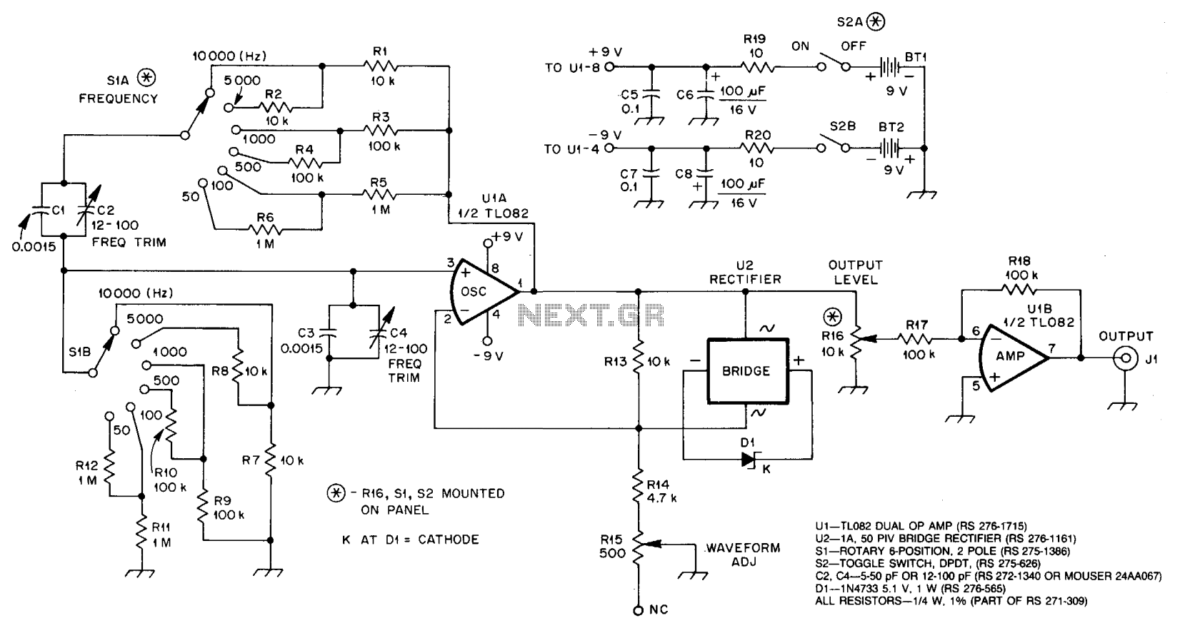
U1A, an operational amplifier, oscillates at the frequency where the phase shift in the Wien bridge network is precisely zero degrees. Adjusting the component values of the bridge alters the oscillator frequency. In this circuit, only the two resistors...
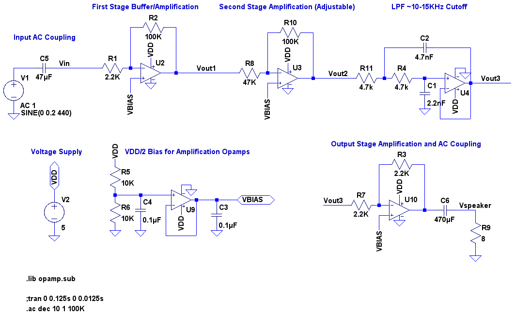
A video showcases a friend, James, playing his electric guitar, connected through an audio echo effect system to an amplifier. The echo effect is implemented on a breadboard rather than through hidden pedals or amp options. Apologies are made...
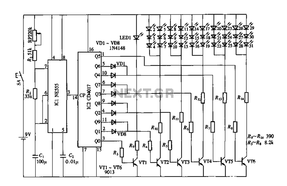
An electronic decorative peacock consists of 10 light-emitting diodes (LEDs), each of which contains multiple LEDs arranged in the tail of the peacock model. The light emission drive circuit operates the fan-shaped LEDs in a cyclic manner, emitting light...
This infrared transmitter utilizes pulse width modulation (PWM). The transmitter is equipped with an LM567 tone decoder circuit. An audio signal (at least 50 mV peak-to-peak) is amplified with transistor T1 and subsequently used to modulate IC1. The frequency...