
Another RF Field Strength Meter

This RF field strength meter circuit is structured to measure the intensity of radio frequency signals in a designated area. The core components include a simple RF signal detector, which can be implemented using a diode or a transistor, and an analog meter to provide a visual indication of the field strength. The use of a single 1.5V battery simplifies the power supply requirements, making this circuit highly portable and easy to deploy in various environments.
The adjustment of capacitor C1 is critical for calibrating the meter to read the maximum signal strength accurately. This capacitor acts as a tuning element, allowing the user to fine-tune the circuit to the specific frequency of interest. The adjustment of resistor R1 ensures that the meter reads zero when no signal is present, which is essential for accurate measurements.
The operational procedure involves first establishing a baseline reading with the transmitter turned off, followed by taking readings at various distances from the antenna while the transmitter is active. This method allows for a comparative analysis of signal strength at different locations, which can be influenced by environmental factors such as terrain and moisture levels in the ground.
Recording the readings in an engineering logbook is important for tracking performance over time and understanding how environmental conditions affect RF propagation. The noted weather conditions, such as whether it has been dry or rainy, can provide insights into variations in signal strength, as moisture can enhance the propagation of RF signals, particularly in certain frequency ranges.
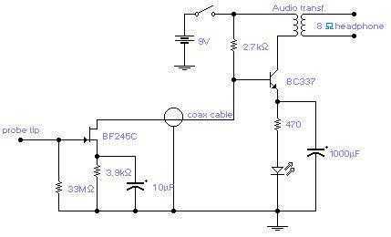
Overall, this RF field strength meter circuit is a valuable tool for RF engineers and hobbyists alike, providing essential data for optimizing antenna systems and understanding radio signal behavior in different environments.This circuit is another radio frequency (rf) field strength meter, similar with our previous field strength meter circuit, but with lower supply voltage (only a single cell 1. 5V battery). Here is the schematic diagram of this rf strength meter circuit: To use, turn on transmitter and meter; adjust C1 for peak reading.
Turn off transmitter and adju st R1 for a perfect zero reading on the meter. Turn on transmitter (with no audio modulation) and go to your monitor point(s) and take readings. Your monitor point(s) should be many meters/yards away from your antenna, but obviously must be where the signal is still strong enough to register on your instrument. After taking a set of readings, you can experiment with your antenna or transmitter system, then take another set of readings and determine whether your signal strength was increased or diminished.
Keep your readings in your engineering logbook. Make note of whether it`s been dry or rainy in recent days; moist soil might give slightly better propagation. 🔗 External reference
Related Circuits
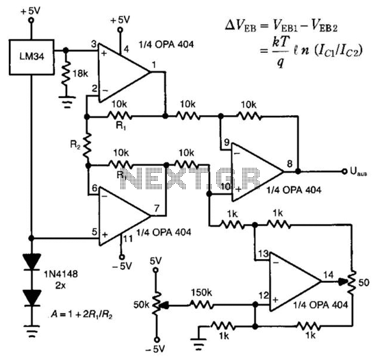
The LM34 is utilized as a sensor in the design of this linear thermometer. Its output represents the difference between two base-emitter voltages (Veb) of two transistors that operate at different collector-current densities. These current densities are denoted as...
The circuit will come handy when you have to follow the mains wires buried in the wall or even water pipes provided they are not too far away (2-4cm max). It will also detect a conversation on a telephone...
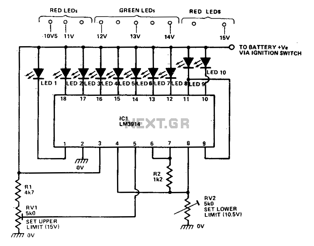
The LM39X4 functions as a LED-driving voltmeter, with its maximum and minimum readings determined by the resistor values R2 and RV2. When properly calibrated, the device operates within a 2-volt to 3-volt range but is designed to read supply...
Electronic potentiometer using a standard CMOS logic and analog multiplexers. Pot have low distortion (0.005% less at 1 V rms) and is it easy for beginners to understand. In the beginning, the art of Hi-Fi, in the absence of...
The temperature measuring range of this electronic thermometer is 0-50 degrees Celsius, with a precision of 0.1 degrees Celsius. The measurement results are intuitively displayed on a digital screen. This electronic thermometer circuit consists of a temperature detection circuit,...
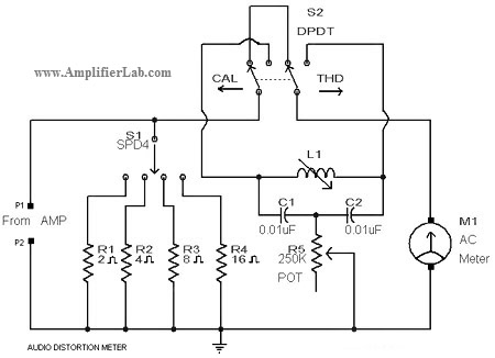
A circuit diagram of an audio distortion meter is presented here. An audio distortion meter is utilized to measure Total Harmonic Distortion (THD). The audio distortion meter is an essential tool in audio engineering, designed to quantify the level of...