
Electronic thermometer(2)
")
The electronic thermometer is designed to accurately measure temperatures within the range of 0 to 50 degrees Celsius, making it suitable for various applications such as laboratory experiments, food safety, and environmental monitoring. The precision of 0.1 degrees Celsius ensures that the readings are reliable and suitable for sensitive measurements.
The temperature detection circuit typically utilizes a temperature sensor, such as a thermistor or a digital temperature sensor like the DS18B20, which converts the temperature into an electrical signal. This signal is then processed by the monostable circuit, which may serve to stabilize the output signal and ensure that the readings are consistent over time.
The digital display drive circuit is responsible for converting the processed signal into a format that can be displayed on a digital screen, usually a seven-segment display or an LCD. This circuit interfaces with the microcontroller or a dedicated driver IC to facilitate the display of temperature readings in real-time.
The power supply circuit provides the necessary voltage and current to the entire system, ensuring that all components function correctly. This circuit may include voltage regulators, capacitors for smoothing, and possibly a battery management system if the thermometer is designed for portable use.
Overall, this electronic thermometer circuit combines multiple components to deliver accurate temperature readings, with a user-friendly digital display that enhances usability in various settings.The temperature measuring range of this electronic thermometer is 0-50?, the precision is 0.1?, the measurement results are intuitively displayed by digital display. This electronic thermometer circuit is composed of temperature detection circuit, monostable circuit, digital display drive circuit and power supply circu..
🔗 External reference
Related Circuits
This electronic lighting dimmer circuit is designed to control the brightness of incandescent lamps, but it is not suitable for fluorescent lamps. It operates with both 110V and 220V AC power sources. The circuit is connected in series with...

The input capacitor is used for low-frequency cut-off, with a standard value of 0.1 µF, resulting in a cut-off frequency of approximately 16 Hz. The input capacitor plays a critical role in electronic circuits, particularly in signal processing and audio...
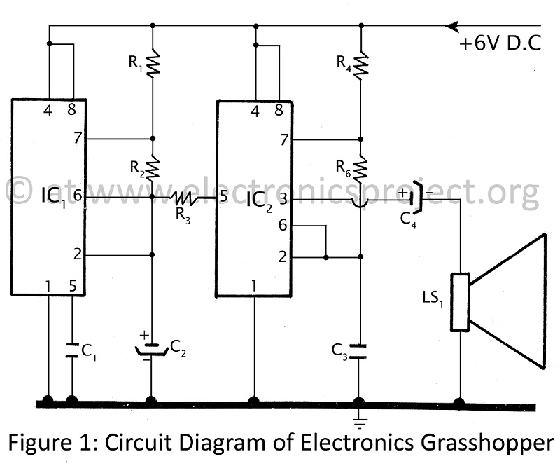
This project is designed for children and electronics beginners. It replicates the sound of a grasshopper or cockroach, producing a shrill noise at night. The circuit, referred to as the Electronics Grasshopper, generates a PI-PI sound and can function...
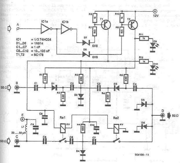
This antenna selector circuit diagram electronic project is constructed using standard electronic components and facilitates the switching between two FM antennas through a logic signal. The gates IC1b and IC1a manage the switching and interface between the required logic...
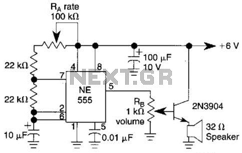
Ra sets the rate while RH sets the volume of clocks in the speaker. The 555 is configured as a low frequency oscillator. The circuit is powered by a 6 V battery. The circuit utilizes a 555 timer IC configured...

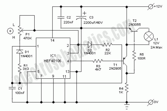
The schematic illustrates the design of a circuit that measures the resistance of the skin and transforms it into a functional switching signal. This circuit typically employs a resistive sensor, often referred to as a skin resistance sensor or galvanic...