
Inexpensive Linear Thermometer

The LM34 linear temperature sensor operates based on the principle of measuring the voltage difference between two transistors that are biased at different current densities. The output voltage is directly proportional to the temperature, which is a key feature for applications requiring precise temperature measurements. The linearity of the output over a wide temperature range makes it suitable for various industrial and consumer applications.
The instrumentation amplifier configuration enhances the signal output from the LM34, providing a high input impedance and low output impedance, which is crucial for interfacing with subsequent processing stages. The design typically involves three operational amplifiers arranged in a differential configuration, where two are used to amplify the sensor output and one is dedicated to offset voltage control. This setup ensures that any variations in the sensor output due to environmental factors can be compensated, maintaining accuracy.
The gain of the instrumentation amplifier is determined by the resistor R2, allowing for flexibility in adjusting the sensitivity of the temperature readings. By selecting different values for R2, the circuit designer can tailor the gain to meet specific application requirements, whether that be for high precision in a laboratory setting or broader ranges in industrial applications.
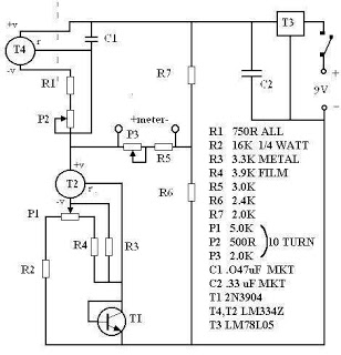
Overall, the combination of the LM34 sensor and the instrumentation amplifier circuit provides a robust solution for accurate temperature measurements, with adjustments for gain and offset that enhance its usability across various applications. As a sensor in the design of this linear thermometer, the LM34 is used. The output is the difference between two base-emitter voltages AVeb °f two transistors operated at different collector-current densities. where the current densities are IC and let, k is Boltzmann"s constant, and q is the electron charge. Because all factors, including the ratio IciUci are constant, the output of the LM34 (National Semiconductor) is a linear function of in the range over - 50° to 300°F, which provides the output voltage of 10 mV/ °F with a max.
nonlinearity of ±0.35°F. The output of the LM34 is amplified by a three-op-amp instrumentation amplifier. The fourth op amp gives the possibility to control the offset voltage of the amplifier. The gain A of the instrumentation amplifier can be set to any desired value by the choice of the resistance R2 only.
Related Circuits
This is a low-cost 150-watt amplifier circuit with a diagram and schematic design utilizing two Darlington power transistors, TIP142 and TIP147. The 150-watt amplifier circuit is designed to provide high power output while maintaining cost efficiency, making it suitable for...
This is a linear frequency modulation (FM) detector circuit. This circuit is commonly utilized in telemetry applications and a wide range of analog communication systems. The primary component of this circuit... The linear FM detector circuit is designed to demodulate...
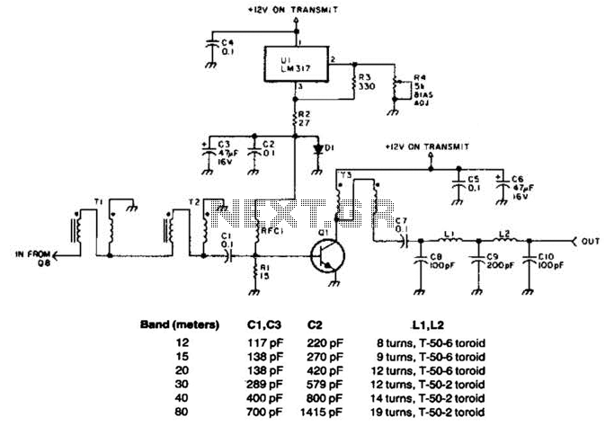
This linear amplifier provides a 10-W PEP output with a 1.25-W drive on the 10 m band. The transformers, T1, T2, and T3, consist of 10 turns of bifilar windings on an FT-50-43 toroidal core and are designed for...
There are many digital thermometers with ±1°C displays, but their accuracy is approximately ±1°C and they cannot be calibrated. A thermometer circuit was created using components available at a local electronics hobby shop, providing an educational experience. For a...
The following circuit illustrates a fully linear diode sensor circuit diagram. This circuit is based on the A748 integrated circuit (IC). Features include the use of an operational amplifier (op-amp). The fully linear diode sensor circuit utilizes the A748 IC...
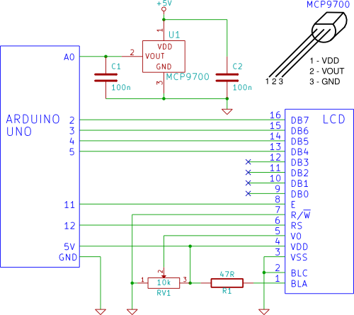
A temperature sensor (MCP9700 linear active thermistor IC) and LCD are connected to the Arduino in this tutorial. The Arduino reads the temperature from the MCP9700 on analog pin A0 and displays the temperature on the LCD. The circuit involves...