
Antenna Booster for FM AM and SW Receiver

The AM/FM antenna booster circuit is an essential component for enhancing radio reception across various frequency bands, including AM (Amplitude Modulation), FM (Frequency Modulation), and SW (Shortwave). The circuit typically consists of a low-noise amplifier (LNA), which is crucial for boosting weak signals captured by the antenna without introducing significant noise.
The circuit design usually incorporates a transistor or an operational amplifier configured in a common-emitter or common-source arrangement to achieve the desired gain. A power supply, often 12V or 9V, is required to power the amplifier. Additionally, decoupling capacitors are included to filter out any power supply noise, ensuring that the amplifier operates efficiently.
Input impedance matching is also a critical aspect of the design to maximize power transfer from the antenna to the amplifier. This is often achieved using a matching network composed of resistors and capacitors. The output stage of the amplifier may include a band-pass filter to ensure that only the desired frequency range is amplified, thus minimizing interference from unwanted signals.
For optimal performance, the antenna booster should be housed in a weather-resistant enclosure if it is intended for outdoor use. Proper grounding techniques must be employed to prevent signal loss and to protect the circuit from lightning strikes. Overall, the AM/FM antenna booster circuit enhances the listening experience by providing clearer and stronger signals across a wide range of frequencies.This AM/FM antenna booster circuit amplify the broadband signal from antenna. This antenna booster should work fro FM, AM, and SW receivers. Here is the.. 🔗 External reference
Related Circuits
A regenerative radio receiver is unsurpassed in comparable simplicity, weak signal reception, inherent noise-limiting and agc action and, freedom from overloading and spurious responses. The regenerative radio receiver or, even super-regenerative radio receiver or, "regen" if you prefer, are...
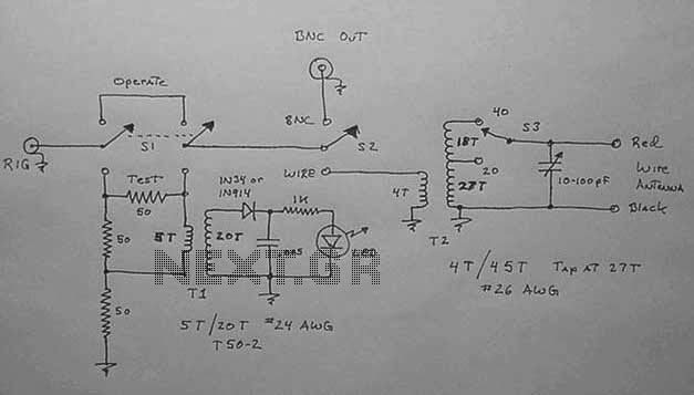
Following the functionality of the standard regenerative front-end receiver circuit, initial output from the transmitter can be observed. The first point of interest in the schematic is located immediately after the LC tuning circuit and the DC blocking capacitor....
This active antenna schematic can be used to frequency range from 10 KHz to 100 MHz. The length of the Antenna can be between 0.5 to 1 meter long. The power consumption is 20-30mA. More: Use the shortest possible...
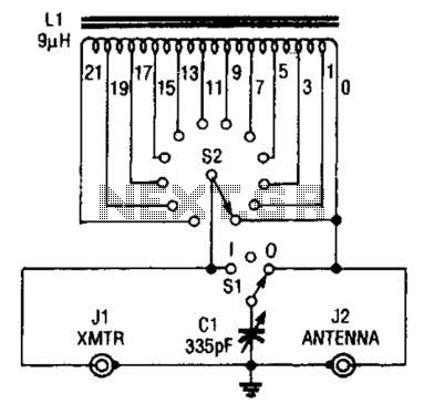
This antenna tuner is designed for low-power transmitters or shortwave receivers with a maximum power output of 5 watts. The switch S2 is used to select the inductance, while S1 connects a 365-pF capacitor either to the transmitter or...
The input impedance of AC-coupled operational amplifier (op-amp) circuits is primarily determined by the resistance that establishes the DC operating point. When using CMOS op-amps, the input impedance is high, reaching up to 10 MΩ in current op-amps. For...
All miniature electronic devices operate on batteries. Some require voltages higher than the standard battery voltages for efficient operation. When a battery of the specific voltage is unavailable, it becomes necessary to connect additional cells in series to increase...