
Low-Power Antenna Tuner Circuit

The antenna tuner circuit operates by matching the impedance of the transmitter or receiver to the antenna, which is crucial for maximizing power transfer and minimizing signal reflection. The tapped inductor (L1) provides multiple inductance values, allowing for fine-tuning of the circuit to achieve the best performance across various frequencies. The variable capacitor (C1) further enhances tuning flexibility by enabling adjustments to the capacitance value, which is essential for resonance matching.
The SPDT switch (S1) plays a vital role in the circuit's functionality, as it allows the user to toggle between connecting the capacitor to the transmitter's output or the inductor's input. This feature is particularly useful for optimizing the circuit's performance for different operating conditions. The configuration is compact, making it suitable for portable applications where space is limited.
Overall, the design of this antenna tuner ensures efficient operation for low-power applications, providing users with the necessary tools to effectively tune their equipment for optimal signal quality. The careful selection of components and the strategic use of switching mechanisms contribute to the overall effectiveness of the tuner in achieving desired performance characteristics. This antenna tuner is suitable for use with low-power (less than 5 W) transmitters or SW receivers. S2 selects inductance and S2 connects the 365-pF capacitor to either the transmitter or the side of the inductor. The tiny tuner is comprised of a tapped inductor (LI) and a variable capacitor (01), which is connected to the inductor through a center-off SPDT switch (SI).
That switch arrangement permits the capacitor to be connected to either the input or the output of the circuit.
Related Circuits
This example describes the use of HS101 and HS201 radio transmitter and receiver modules to control rotating color lights, functioning as a multi-channel radio remote control device suitable for small dance floors or home use. Users positioned at any...
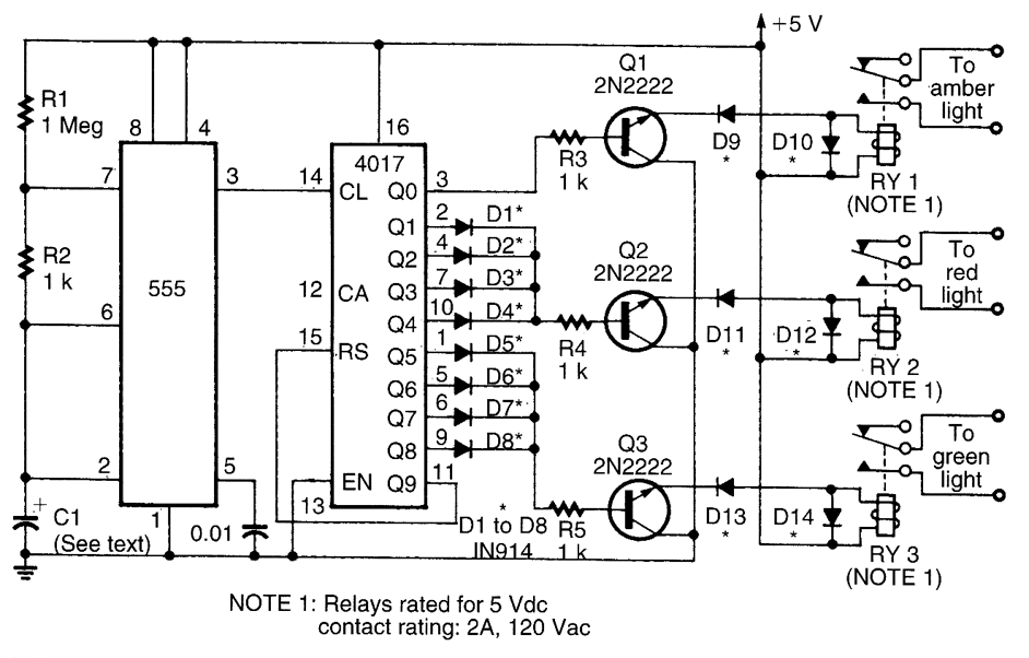
This circuit utilizes a 555 timer to control a 4017 decade counter. The outputs from the counter are used to drive transistor relay drivers. The duration for which the lights remain "on" can be adjusted by modifying the connections...
The program utilizes the Linear LT1934 chip for the production of a high-efficiency power supply circuit design that is less demanding in terms of electrical load. It offers considerable adjustment margins. When supplied with a 24VDC input, the non-isolated...
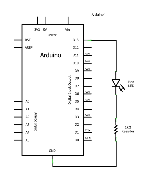
Arduino consists of two main components: the hardware (the Arduino board) and the software (the IDE). The advantage of using Arduino is that circuits can be built and their behavior modified by altering the code instead of changing the...
This circuit incorporates a Very Low Frequency (VLF) Amplitude Modulation (AM) component into an audio signal. This effect is commonly utilized in musical instruments. U1C, a phase-shift oscillator functioning at a few Hertz, generates a signal that modulates the...
This circuit generates a two-tone effect similar to the cuckoo song. It can be utilized for doorbells or other applications due to its integrated audio amplifier and loudspeaker. When used as a sound effect generator, it can be connected...