
APM-81 elevator control cabinet circuit

The APM-81 lift system is designed with a comprehensive electrical architecture that integrates a main circuit, a safety circuit, and a brake circuit, ensuring reliable operation and enhanced safety measures.
The main circuit is responsible for powering the lift's motor and controls, facilitating the vertical movement of the lift car. This circuit typically includes components such as a power supply, motor controller, and various relays that manage the operation of the lift. The motor controller regulates the speed and direction of the lift, while the relays provide switching capabilities for different operational modes, such as ascent and descent.
The safety circuit is a critical component that monitors the lift's operational parameters to prevent accidents. It includes safety switches, limit switches, and emergency stop buttons. These components work together to ensure that the lift does not operate under unsafe conditions, such as when doors are open or when the lift exceeds its designated travel limits. The safety circuit is designed to immediately cut power to the lift in case of a malfunction, thereby preventing potential hazards.
The brake circuit is essential for controlling the lift's stopping mechanisms. It typically consists of an electromechanical brake that engages when the lift is not in motion, holding it securely in place. When the lift is in operation, the brake circuit ensures that the braking system is activated during descent and can be engaged quickly in case of an emergency. This circuit may also include sensors that monitor the lift's speed and position, allowing for precise braking control.
Overall, the integration of these circuits within the APM-81 lift system provides a robust framework for safe and efficient lift operation, prioritizing user safety and system reliability.APM-81 lift the main circuit, the safety circuit and brake circuit:
Related Circuits
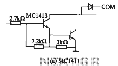
The MC1411 series is a Darlington driver with a compact, reliable internal structure. It is particularly suited for high-voltage applications, functioning effectively as a high-voltage peripheral driver. This driver can directly control relays, lights, and other loads. It is...
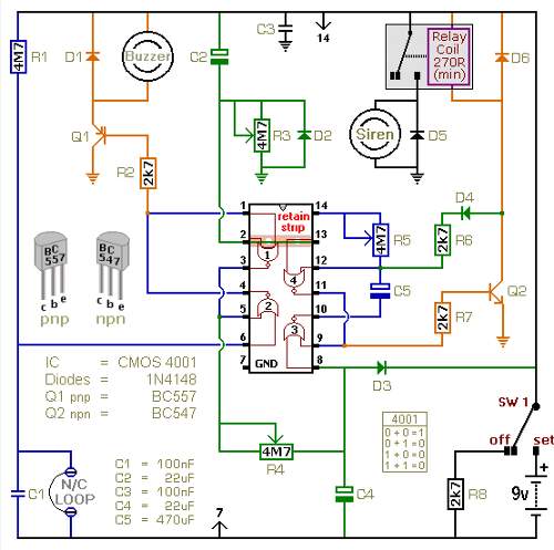
The following circuit illustrates a battery-powered burglar alarm sensor circuit. Features include foil tape and passive infrared sensors (PIRs), as well as magnetic reed contacts. This battery-powered burglar alarm sensor circuit is designed to provide an effective security solution for...
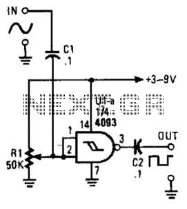
This circuit converts a sine wave into a square wave. It consists of a single 2-input NAND Schmitt trigger configured as an inverter, with an adjustable trigger level at its input. As the input voltage exceeds the gate's trigger...

Switch-mode driven 1.5V bulbs. This device was designed on request, to control the light intensity of four filament lamps (i.e. a ring illuminator) powered by two AA or AAA batteries, for close-up pictures with a digital camera. Obviously it...
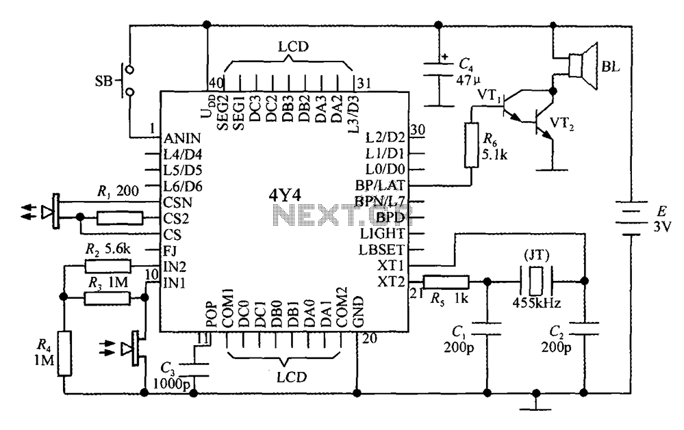
The 4Y4 is a monolithic liquid crystal display rangefinder circuit. The instrument comprises an ultrasonic transmitter, a receiver, an LCD display, buttons, switches, and a buzzer (or speaker). To simplify wiring, the 4Y4 is directly welded to the back...
The PowerSaver Flasher uses capacitive output coupling to produce brighter shorter flashes and has a much lower average current drain than standard bicore or 74HC14 flashers. The PS Flasher with one LED circuit (2 LEDs) runs all night from...