
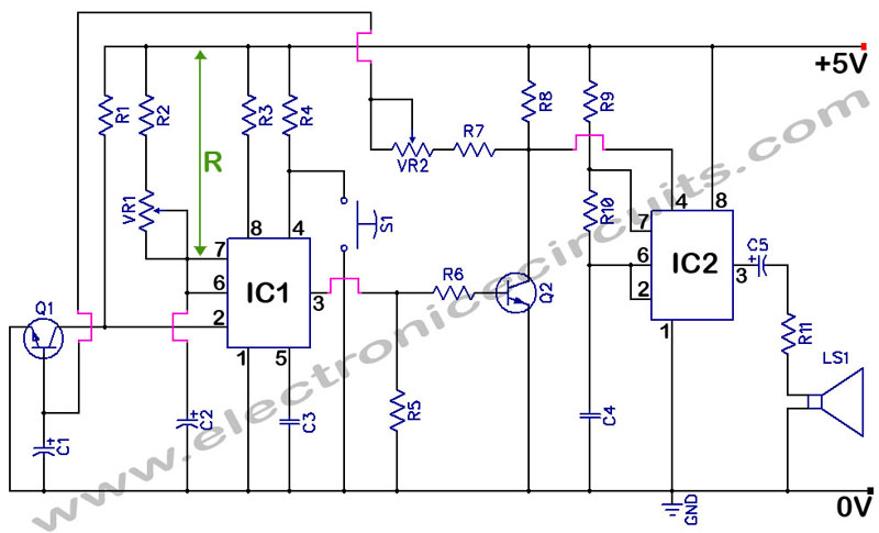
Aquarium Led Lighting Circuit

The aquarium LED lighting system enhances the aesthetic appeal of the aquarium by simulating natural lighting conditions. The circuit typically consists of a microcontroller or timer that detects the ambient light levels, allowing the LEDs to illuminate the tank at dusk.
The key components of the circuit include:
1. **LEDs**: High-efficiency RGB LEDs are used to create vibrant colors that mimic natural underwater lighting. The selection of colors can enhance the visibility of fish and aquatic plants, creating a visually appealing environment.
2. **Microcontroller**: A microcontroller, such as an Arduino or a dedicated timer chip, is programmed to monitor light levels. It activates the LEDs based on the time of day or ambient light detected by a light sensor, ensuring that the aquarium is lit during the evening hours.
3. **Light Sensor**: A photoresistor or phototransistor can be employed to monitor the surrounding light conditions. When the ambient light falls below a certain threshold, the sensor sends a signal to the microcontroller to turn on the LED lights.
4. **Power Supply**: The circuit requires a suitable power supply to drive the LEDs. This could be a standard AC to DC adapter or a battery pack, depending on the design requirements and power consumption of the LEDs.
5. **Control Circuitry**: Additional components such as resistors, capacitors, and transistors may be used to control the current flowing to the LEDs, ensuring they operate within safe limits and prolonging their lifespan.
This lighting system not only enhances the visual appeal of the aquarium but also contributes to the well-being of the aquatic life by mimicking natural day-night cycles. Proper implementation of this circuit can result in an energy-efficient and aesthetically pleasing aquarium setup.This colorful back led aquarium lights gives natural appearance to the Aquarium tank. The Aquarium Led Lighting circuit automatically turns on at sunset an.. 🔗 External reference
Related Circuits
555 Timer with Audio Alarm Circuit. This circuit serves as a straightforward electronic timer equipped with an audio alarm feature. The 555 timer is a versatile integrated circuit widely used in various timer, delay, pulse generation, and oscillator applications. In...
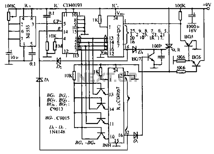
The circuit consists of an oscillator, a counter, and an Iseki circuit divided into three parts. The oscillator is based on the NE555 timer and several external RC components, generating a pulse signal for the counter. The instantaneous power...
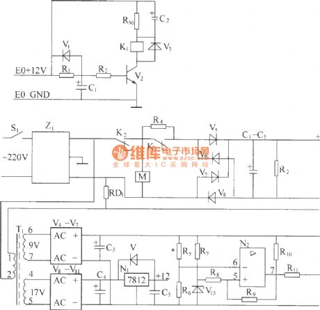
220V (50Hz) alternating voltage passes through the Z1 circuit filter, which filters the signal before sending it to the connection point of the AC overvoltage and undervoltage protection relay K2. During normal operation, the K2 connection point should be...
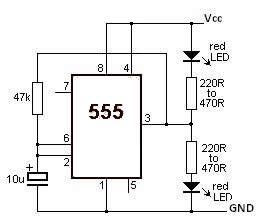
This LED flasher circuit utilizes a 555 timer integrated circuit (IC). The circuit diagram is straightforward and requires only a few external components. When operational, the red LEDs will flash sequentially at a predetermined frequency, similar to the indicators...
This is a circuit diagram for a simple doorbell. The circuit can be assembled indoors, while the switch should be placed outside, making it easily noticeable for visitors. The operation of this circuit is similar to a previous project. The...
This is a stereo power amplifier circuit that operates at up to 22W per channel, resulting in a total output of 2x22W. A few external components are required to support the main component, the TDA1554. A heatsink on the...