
Infrared Remote Control Switch

The infrared remote control switch circuit utilizes an infrared (IR) transmitter and receiver to enable wireless operation of various devices. The circuit typically consists of a microcontroller, an IR LED, a photodiode or phototransistor, and several passive components such as resistors and capacitors.
The IR transmitter emits modulated signals that carry control commands. When the remote control button is pressed, the microcontroller generates a specific binary code, which is then converted into an IR signal by the IR LED. The modulation of the signal ensures that the receiver can differentiate between different commands.
On the receiving end, the photodiode or phototransistor detects the incoming IR signals. The output of the photodiode is fed into a microcontroller, which interprets the received signals and executes the corresponding action, such as turning a device on or off. The circuit may also include a relay or a transistor to handle higher power loads, allowing control of devices like lights or fans.
The design of the circuit can be adapted for various applications by modifying the code in the microcontroller or changing the configuration of the components used. This flexibility makes the infrared remote control switch circuit an ideal solution for remote operation in home automation systems, entertainment devices, and other electronic applications.
Overall, the infrared remote control switch circuit offers a convenient and efficient way to control devices wirelessly, enhancing user experience and operational efficiency.Infrared Remote Control Switch Circuit Remote controls, specially cordless type, are very popular nowadays. Here is a simple and.. 🔗 External reference
Related Circuits
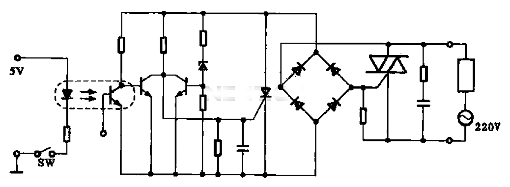
This application example illustrates a photovoltaic control circuit. In this circuit, the Triac functions as a solid-state relay, providing an AC power supply path to the load. It is designed to achieve high current control signals using a small...
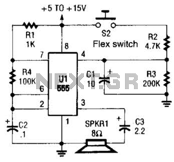
This is a cross-sectional diagram of a flex switch. They can be used as pushbuttons or even position sensors. This schematic diagram shows an oscillator, which is used as an alarm sounder, triggered by a flex switch. The flex switch...
This project is a remote control system based on a PIC and a universal remote controller for TV, named SIMPLEX. The IR signal of a specific remote controller is received from an IC receiver (SFH 505 or similar) and...
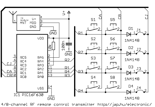
This is a general purpose remote control project with using programmable PIC microcontrollers. Schematics are shown for using infrared (RF) or radio (RF) media. If you are not familiar with microcontroller programming, you can use fixed encoder and decoder...
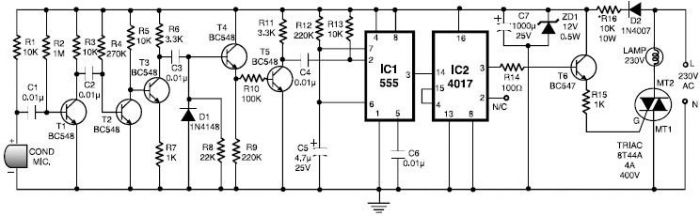
This 555 timer clap switch circuit electronic project is designed using common electronic components. The circuit operates from a distance of up to 10 meters from the microphone. The signal from the microphone is amplified by transistors T1, T2,...
This circuit allows for the adjustment of fan speed from a distance, such as from a couch or bed. It utilizes the TSOP1738 infrared receiver module to capture the infrared signals. The circuit operates by employing an infrared remote control,...