
Arduino Blinky LED Intro Circuit

The schematic involves a straightforward connection of a 5mm LED to the Arduino Uno's digital output pin 12. The LED is a simple light-emitting diode that requires a forward voltage to operate correctly. In typical applications, a current-limiting resistor is used in series with the LED to prevent excessive current that could damage the component. However, for short-term testing purposes, the LED can be directly connected to the digital output pin, as the Arduino's output is designed to handle the current for brief periods without causing harm.
The Arduino Uno serves as the microcontroller platform, featuring an ATMega328P microcontroller, which is programmed via the Arduino IDE. The USB connector allows for easy programming and power supply, while the DC power jack enables mobile operation when an external power source is connected. The schematic illustrates the connection from the digital output pin to the anode of the LED, with the cathode connected to the ground. This configuration allows the LED to illuminate when the output pin is set to HIGH.
For testing purposes, a simple Arduino sketch can be uploaded to toggle the state of digital output pin 12. This sketch could include basic commands such as `digitalWrite(12, HIGH)` to turn on the LED and `digitalWrite(12, LOW)` to turn it off. This demonstration serves as a basic introduction to digital output control, showcasing the fundamental principles of interfacing components with the Arduino platform. The simplicity of this project makes it an excellent starting point for those new to electronics and programming with Arduino.The schematic for this project really only consists of adding a single 5mm LED to one digital output port on the Arduino. The picture below should be fairly self explanatory for how to do it. The main parts in the schematic are the Arduino Uno, 5mm LED and USB Cable. The far left side of the Arduino board (as seen above) has both the DC power j ack to supply power for mobile operation and the USB connector for supply power + programming. This USB connector actually connects to a seperate Atmel microcontroller which acts like a translator to convert USB to serial information passed on to our ATMega328 that the Arduino bootloader understands. The 5mm LED that we will add to the digital output 12 will be used to help prove that we can run both a standard example program and a modified Arduino program.
Normally a current limiting resistor should be placed before LEDs, in this case since we won`t be using the LED or Arduino in this configuration for months on end, the LED will not be damaged by connecting straight to a digital output. This is the platform that I am using, however you are free to use any of the standard Arduino platforms as they all have similar features and you can follow along with this article no matter which one you have.
🔗 External reference
Related Circuits
The goal was to create a compact flashlight that could be held in the mouth, easily stored in a pocket, and positioned on a surface to project light upwards. The budget was set at approximately $15, which was significantly...
The chip in the center with small bullet holes is likely proprietary. It is possible to salvage a few components from it, although understanding the circuit is not necessary for this purpose. Additionally, it is confirmed that the device...

The thermistor RT, along with resistors R1, R2, R3, and variable resistor RP1, creates a temperature measurement bridge. At a temperature of 20°C, the configuration of R1, R3, and the adjustment of RP1 enables the bridge to maintain balance....
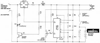
This circuit illustrates a Lithium Battery Charger circuit diagram. Charging is achieved using a constant current of 60 mA for AA cells until a cutoff voltage of 2.4V per cell is reached, at which point the charging process must...
The use of diode rectifiers in AC voltmeters with a low lower limit of measurement range (0.5-1 V) leads to significant nonlinearity of the scale due to the nonlinearity of the current-voltage characteristics of diodes. The incorporation of electronic...
This circuit illustrates the TDA1054 tone control stereo preamplifier circuit diagram. Features include the National Semiconductor LM35 integrated circuit, which utilizes semiconductor technology. The TDA1054 is a versatile integrated circuit designed for use in audio applications, particularly in tone control...