
pcb Help identifying and finding shematics/datasheets for circuit board

The optical PC mouse operates using a light-emitting diode (LED) and a photodetector to detect movement across a surface. The proprietary chip serves as the core processing unit, interpreting the signals from the optical sensor and translating them into cursor movement on the computer screen. The optical sensor captures images of the surface at a rapid rate, typically thousands of times per second, allowing for precise tracking of motion.
The LED illuminates the surface beneath the mouse, and the optical sensor detects the light reflected back from the surface. Variations in the reflected light caused by changes in surface texture are processed by the chip, which calculates the direction and speed of the mouse's movement. This information is then sent to the computer, enabling the cursor to move correspondingly.
In terms of components, the optical PC mouse typically includes the following: the LED (often a red or infrared light), the optical sensor (which may be a CMOS or CCD type), the proprietary chip for processing, and various passive components such as resistors and capacitors that help regulate power and signal processing. The design of the circuit is crucial for optimizing the performance of the mouse, ensuring accurate tracking and responsiveness to user input. The integration of these components is often done on a printed circuit board (PCB) that supports the physical layout and electrical connections necessary for the mouse to function effectively.The chip in the middle with the tiny bullet holes in it is almost certainly proprietary. At best you can salvage a few parts if your time is worth nothing, but you don`t need to know the circuit for that. Olin Lathrop Apr 9 `13 at 14:24 Just to make sure: you do know it`s an optical PC mouse, right The chip in the middle that Olin mentioned is an optical sensor.
m. Alin Apr 9 `13 at 14:38 I was getting only a page with "Kommentarer - RapportG©r bilde. Husk G¥ inkludere adressen til bildet. " and no images. Oh well, YMMV Madmanguruman Apr 10 `13 at 18:14 🔗 External reference
Related Circuits
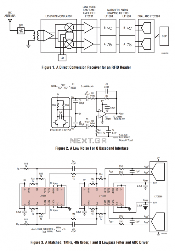
Figure 1 shows the block diagram of a direct conversion RF receiver—the receiver demodulates an RF carrier directly into a baseband signal without an intermediate frequency down-conversion (a zero IF receiver). The antenna, shared by both the transmitter and...
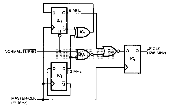
This circuit generates a dual-speed clock for personal computers. It synchronizes asynchronous switch inputs with the master clock to provide glitch-free transitions between clock speeds. The dual-speed clock allows certain programs to operate at a higher clock speed for...

This topic will be locked and will display all of the circuits and some photos of the devices being worked on in the Joule Thief topic. This process will take some time, so patience is appreciated. If any errors...
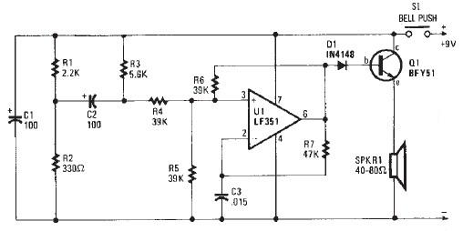
This electronic door buzzer circuit schematic has a straightforward function and is simple to construct. The circuit employs an LF351 operational amplifier along with a few common electronic components. When the S1 push-button is pressed, a positive voltage is...
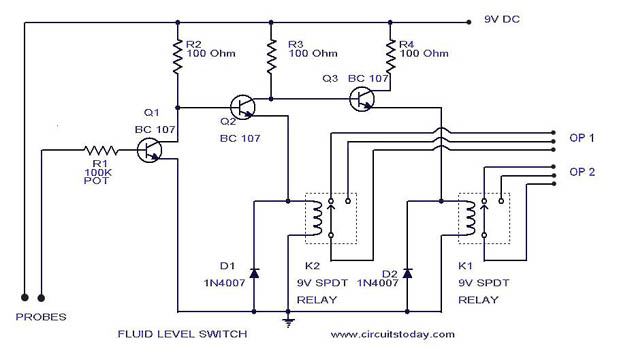
A simple liquid level switch circuit with diagram and schematic. This can also be used as a water level switch, fluid level switch, float level switch, and tank level switch. The liquid level switch circuit is designed to detect the...
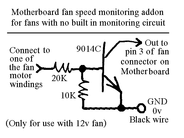
You will find this identical circuit inside most 3 wire computer fans with speed monitoring output to the motherboard. Peel off the sticker from the fan hub in order to access a motor winding pin for connecting up the...