
arduino code for buffalo ii dac lcd connection

The integration of a standard LCD with an Arduino microcontroller involves establishing specific connections that facilitate communication and control. The typical configuration includes connecting the LCD's data pins to designated digital pins on the Arduino, often using pins 2 to 7 for a 16x2 character LCD. The control pins, including the Register Select (RS), Read/Write (RW), and Enable (E), must also be connected to appropriate digital pins on the Arduino to manage data transmission effectively.
The LCD requires a power supply, typically 5V, which can be derived from the Arduino's power output. It is essential to connect the ground (GND) of the LCD to the ground of the Arduino to ensure a common reference point. Additionally, a potentiometer is often used to adjust the contrast of the LCD. This potentiometer is connected between the V0 pin of the LCD and ground, with the wiper connected to the V0 pin, allowing for manual adjustment of the display contrast.
The standard LCD library provided by Arduino simplifies the programming aspect. By including the library in the Arduino IDE, users can easily send commands and data to the LCD using predefined functions. The initialization of the LCD typically involves setting the number of columns and rows, followed by clearing the display and setting the cursor position for text output.
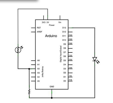
This setup is widely used in various applications, including simple user interfaces, data display for sensors, and interactive projects, showcasing the versatility of the Arduino platform in handling LCD displays.For a good tutorial in hooking up a ""standard"" LCD to Arduino and use the standard LCD library, see: LadyAda Tutorial on LCDs The diagram shows the basic connections with a ""standard"" LCD that is also compatible with the current Arduino LCD library. Adjustment for the contrast is manual with.. 🔗 External reference
Related Circuits
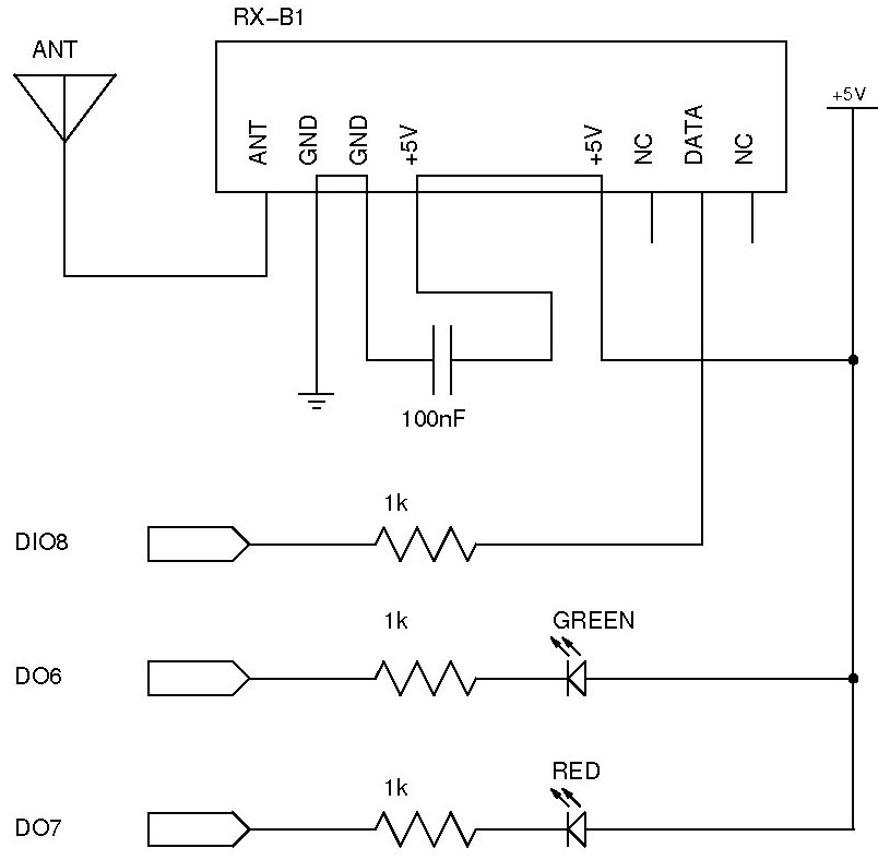
The documentation and code cleaning for the Jaycar Thermor/BIOS branded wireless weather station receiver has been completed. The code is based on the Practical Arduino weather station receiver project. The process involved analyzing the RF signal from the weather...
Government data sets available online are often sourced from major metropolitan areas or infrastructural centers. With an easy-to-follow introduction to new software and technologies, the urban sensor kit allows anyone to obtain location-specific information and share it with a...
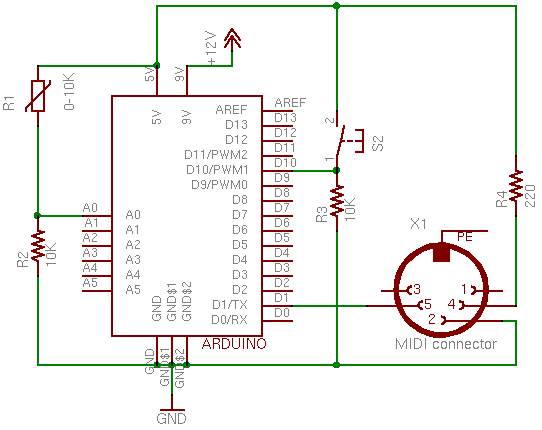
This page covers only the details of MIDI communication on the Arduino module. For a more general introduction to MIDI on a microprocessor, see the MIDI notes on Tom's physical computing site. MIDI, the Musical Instrument Digital Interface, is...
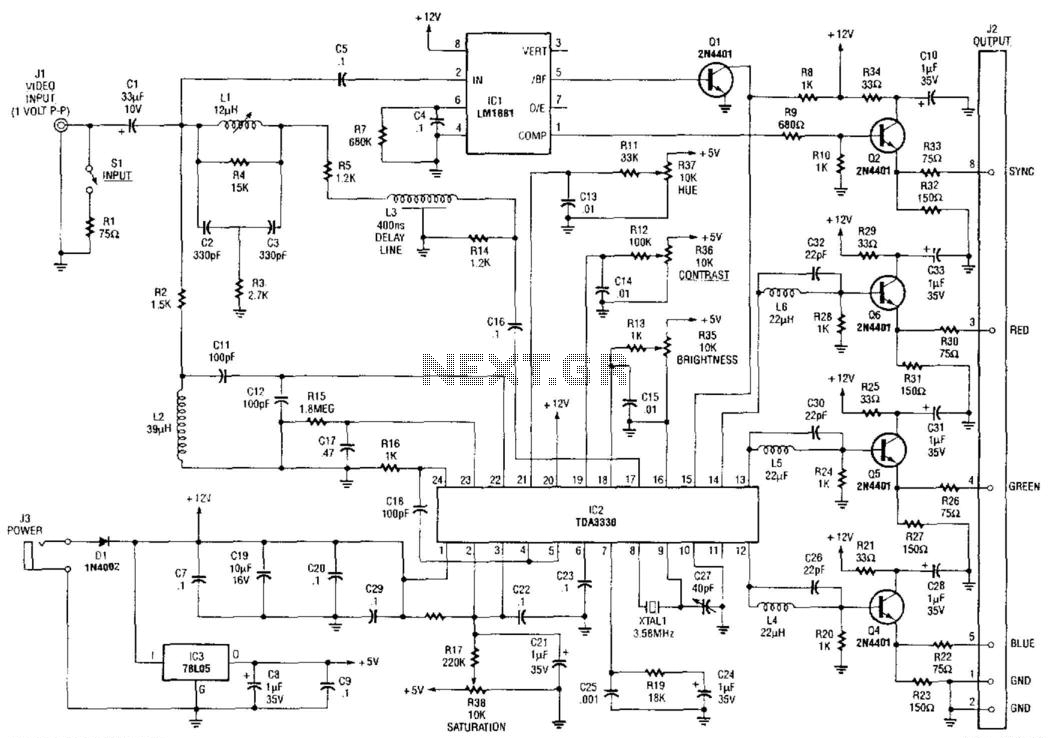
An NTSC/RGB decoder is presented here. Utilizing a TDA3330, a 1-V input video signal is decomposed into its red (R), green (G), and blue (B) components, along with composite sync. U1 serves as an integrated sync separator (LM1881). This...
The LM35 from National Semiconductor is a precision centigrade temperature sensor that provides an analog output voltage. It operates within a temperature range of -55°C to +150°C and has an accuracy of ±0.5°C. The output voltage corresponds to 10mV...
This page's mission is to assist in understanding the use of the STA013 MP3 decoder chip for designing an MP3 player. The player design outlined in subsequent pages utilizes the STA013, but this page aims to clarify the STA013...