
arduino LCD thermometer

The circuit involves an MCP9700 temperature sensor, which is a linear active thermistor IC capable of providing a voltage output that corresponds to the temperature. The output voltage from the MCP9700 is proportional to the temperature, typically with a scale factor of 20 mV/°C. This output is connected to the analog input pin A0 of the Arduino, which is responsible for reading the sensor's voltage.
The Arduino processes the analog voltage signal received from the MCP9700. Using the analog-to-digital converter (ADC) built into the microcontroller, the Arduino converts the analog voltage into a digital value that represents the temperature. The formula to convert the ADC value back to temperature in Celsius is:
\[ \text{Temperature (°C)} = \left( \frac{\text{ADC Value} \times \text{V}_{\text{ref}}}{1023} - 0.5 \right) \times 100 \]
where \( \text{V}_{\text{ref}} \) is the reference voltage of the Arduino, typically 5V.
The LCD is interfaced with the Arduino to display the temperature readings. A common choice for this application is a 16x2 character LCD, which requires a few additional components, such as a potentiometer for contrast adjustment and appropriate connections to the Arduino. The LCD operates using a specific library that simplifies communication with the Arduino, allowing for easy display of the temperature readings.
The connections between the MCP9700, Arduino, and LCD must be correctly established for the circuit to function properly. The MCP9700's VCC pin is connected to the Arduino's 5V output, the GND pin to the Arduino's ground, and the output pin to analog pin A0. The LCD is connected according to its specifications, typically using digital pins for data and control signals.
This setup demonstrates a basic yet effective way to monitor and display temperature using an Arduino platform, combining the simplicity of the MCP9700 sensor and the versatility of an LCD for visual output.A temperature sensor (MCP9700 linear active thermistor IC) and LCD are connected to the Arduino in this tutorial. The Arduino reads the temperature from the MCP9700 on analog pin A0 and displays the temperature on the LCD..
🔗 External reference
Related Circuits
Sometimes, it is necessary for a program to halt execution while a specific condition remains true. This can be accomplished using a while loop. The following example illustrates the application of a while loop to calibrate the value of...
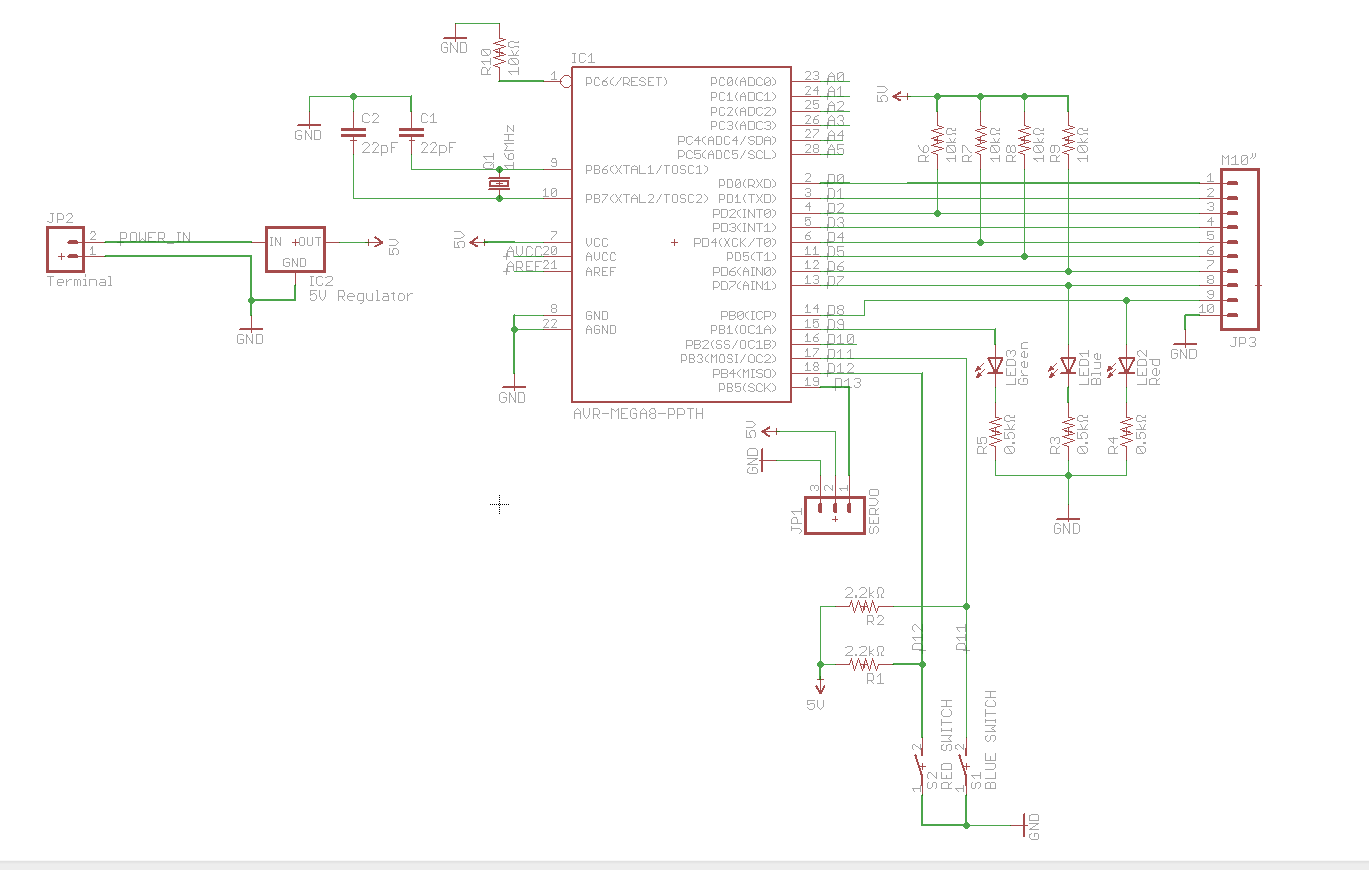
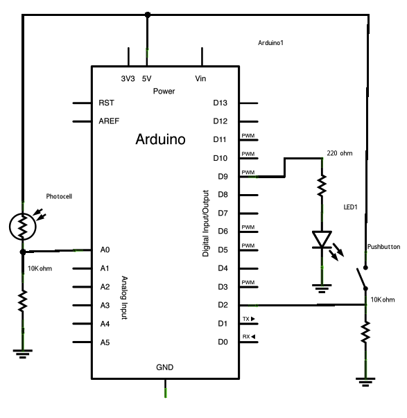
A circuit utilizes a keypad, a servo, and several LEDs, connected to an Arduino Uno. The objective was to integrate all components onto a single PCB, effectively creating a custom version of the Arduino. Upon startup, the red LED...
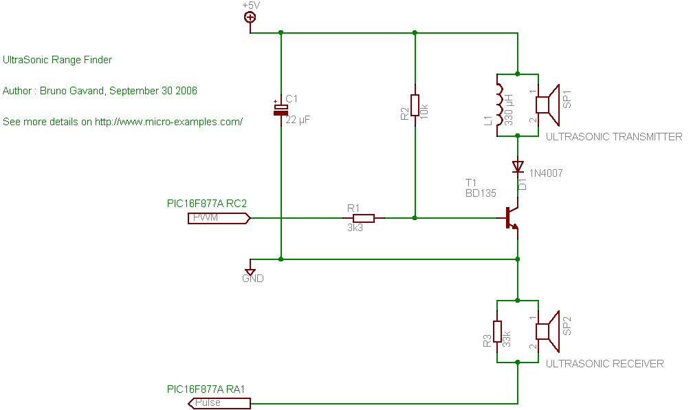
A cat deterrent system utilizing an Arduino, similar to existing models. Detection has been successfully implemented, and it has been determined that an ultrasonic transducer is required to generate the necessary deterrent sound. The proposed cat deterrent system employs an...
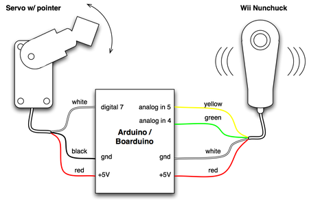
The small footprint of the Boarduino prompted an exploration into how compact a device could be created in one hour using various complex components. The combination of a Boarduino, a Wii Nunchuck, and a hobby servo motor was chosen...

The schematic for this tutorial is illustrated below and includes all necessary components for the tutorial to function. The PIC programming circuitry is not included, as it is assumed that the PIC is either programmed externally or that the...
INTRODUCTION It is essential to monitor the operation of nearly all automated and semi-automated devices, such as washing machines and autonomous systems. Monitoring the functionality of automated and semi-automated devices is crucial for ensuring optimal performance and reliability. This can...