
Custom Arduino circuit not working

The described circuit consists of several key components: a keypad for user input, a servo motor for mechanical movement, and LEDs for visual feedback. The integration of these elements onto a single PCB is a common practice for creating compact and efficient designs. The Arduino Uno serves as the microcontroller, managing the inputs from the keypad and controlling the outputs to the servo and LEDs.
The keypad is typically connected to the Arduino using a matrix configuration, allowing multiple buttons to be read with fewer pins. Each button press can trigger specific actions, such as moving the servo to predefined positions or turning the LEDs on and off. The servo motor, which is powered by the circuit, is expected to respond to commands issued by the Arduino, moving to a designated angle upon initialization.
The red LED serves as an indicator, providing visual confirmation that the circuit is functioning as intended. When the circuit is powered, the LED should light up, signaling that the system is active. If the LED does not illuminate, it may indicate an issue with the circuit connections, the power supply, or the programming on the Arduino.
In the case where the servo is powered but does not perform the expected movements, it is essential to check the following: the programming logic in the Arduino code, the physical connections between the servo and the PCB, and whether the servo is correctly calibrated to respond to the commands issued. Additionally, it may be worthwhile to verify that the power supply is sufficient to meet the servo's operational requirements.
The design of the PCB should also be examined for potential issues such as short circuits, incorrect component placements, or insufficient grounding, which could affect the performance of the entire circuit. By addressing these factors, the functionality of the circuit can be restored, ensuring that both the LED and the servo operate as intended.A circuit using a keypad, a servo and a few LED`s. This was connected to my Arduino Uno. Now I tried putting everything onto a single PCB and thus building my own custom "Arduino" into it. The red LED is supposed to shine and the servo must move to a certain position upon startup, but it does not happen - the servo does get power and keeps it reacts in two ways: 🔗 External reference
Related Circuits
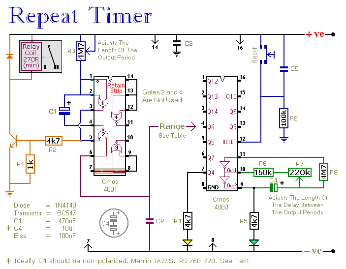
This circuit features an adjustable output timer capable of re-triggering at regular intervals. The output duration can range from a fraction of a second to over half an hour, and it can be configured to recur at regular intervals...

This circuit diagram for a 12V inverter is simple to construct and utilizes inexpensive components that many electronics hobbyists may already possess. While it is feasible to create a more powerful circuit, the complexity arises from managing the significant...
One cannot expect high performance from a basic detector-based meter. Its sensitivity is merely sufficient to provide a fundamental understanding of the power output that the transmitter can achieve. The detector-based meter operates on a straightforward principle where it measures...
The circuit is designed for high precision operation over an extended temperature range, provided that V+ remains relatively constant, as the current IZ is dependent on V+. Resistors R1, R2, R3, and R4 are selected to ensure the appropriate...
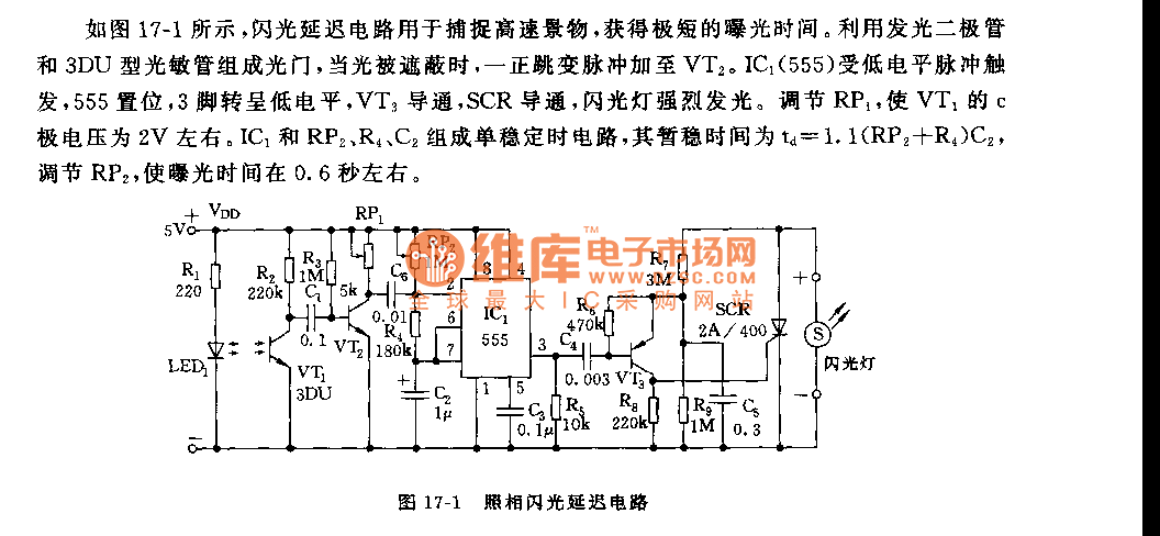
As shown in figure 17-1, the camera flash delay circuit is designed to capture high-speed scenes, allowing for very short exposure times. The light gate consists of a luminous diode and a 3DU type photosensitive tube. When the light...

Electronic FM Telephone Transmitter Schematic. The following schematic design illustrates a circuit diagram for an FM telephone transmitter built on a compact PC board layout. This small design allows it to be easily integrated within the housing of a...