
arduino pulse to transistor power maximum

In this circuit configuration, the power supply strategy is crucial for optimal performance and signal integrity. The Arduino can be powered via USB, allowing for convenient programming and debugging, while the transistor, which handles higher currents, is powered directly from the battery. This separation minimizes potential noise and ensures that the Arduino operates reliably without interference from the power demands of the transistor circuit.
The placement of the analog meter is critical for accurate current measurement. When measuring the current through the transistor, the meter should be placed in series with the load (the coil), allowing it to measure the collector current directly. For total current measurement, the meter must be positioned in the battery circuit, ensuring that all current flowing to the Arduino and the transistor passes through the meter, providing a comprehensive view of power consumption.
The use of a base resistor is essential to protect the Arduino pin and control the base current into the 2N3055 transistor. The recommended 220 Ohm resistor ensures that the base current remains within safe limits while providing sufficient drive to saturate the transistor during operation. This configuration will allow the transistor to act effectively as a switch, controlling the high voltage coil with minimal losses.
In addition, the introduction of an optoisolator is recommended to further isolate the Arduino from the high-power circuit. This component will help mitigate noise and protect the Arduino from voltage spikes that may occur during the switching of the high voltage coil.
Switching to a MOSFET can enhance efficiency, as MOSFETs typically exhibit lower on-resistance (Ron) compared to bipolar junction transistors (BJTs) like the 2N3055. This results in lower power dissipation and heat generation, which is particularly advantageous in high-current applications. The choice of MOSFET should be based on the maximum current and voltage ratings required for the application, ensuring it can handle the demands of the microwave transformer coil without overheating.
Overall, careful consideration of component selection, circuit configuration, and measurement techniques will lead to a robust and efficient design capable of handling the specified requirements.If they have to be both powered from the battery do I need to connect the emitter to the ground of the Arduino AND the battery to stop all the current from flowing through the Arduino ground and get a clean pulse or do I just connect the emitter to the battery negative and the signal will be OK. In whatever configuration is best where is the best place to put a analog meter that is rated up to 3 amps
so that I can see total power consumption of the board and the transistor circuit. Lastly I am using this to pulse the high voltage side coil in a microwave transformer so it has a lot of impedance and when pulsing it it draws about 300 mA max so could I power the Arduino via USB and the transistor from the battery so that I can reprogram on the fly and have a set pulse instead of using the pot. (as in write the code for a certain delay and upload while running) Is it intentional to have a varying delay of n milliseconds, where n is the value read from port A0 each time Also, is that delay required twice, once after setting the output pin high, once after setting it low You will require a base resistor between pulse (Pin 8) and the Base of the 2n3055, with a value calculated depending on how much current you intend to allow through the Collector.
If you are using the transistor as a switch, then a minimum of around 220 Ohms is suggested, to keep current from the pulse pin under around 25 mA, well within the safe limits for each pin: Absolute Maximum for each pin is rated at 40 mA. You could power the Arduino from USB and the transistor from the battery, so long as the ground of the Arduino is connected to the negative pole of the battery.
Put it in series with the coil you are driving, if you want to measure the coil (the transistor`s Collector) current. If you want to measure the combination, both Arduino and transistor need to be powered from the battery, and just add the meter in series with either the positive or negative pole of the battery, before any connection to either Arduino or transistor.
i. e. all current to the battery must pass through the meter. 2) Current will find the path of least resistance, so that`s fine. I would use an optoisolator to separate the two devices. Whenever you switch a large current load, a lot of noise will be induced into your system. 4) I would recommend changing to a MOSFET instead of using the NPN transistor. If you do the power dissipation calculation for the two devices, it makes a lot of sense: MOSFET: P = (I2)(Ron) = (300mA2)*(mOhms) => little heat NPN: P = (I*V) = (300mA)*(0. 7V) = 0. 21W 🔗 External reference
Related Circuits
This simple flashing light circuit operates at 6 volts and 0.5A, exhibiting low current consumption when the light bulb is turned off. The frequency of the flashing is predetermined. The circuit consists of a power supply, typically a battery or...
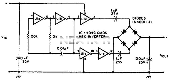
This circuit will provide a negative DC voltage that is approximately equal to the positive input voltage at no load and about 3 V less at a 10 mA load. The input voltage range is from +5 to +15...
This circuit is intended to indicate the power output level of any audio amplifier. It is simple, portable, and displays three power levels that can be set to any desired value. IC1A is the input buffer, feeding 3 voltage...
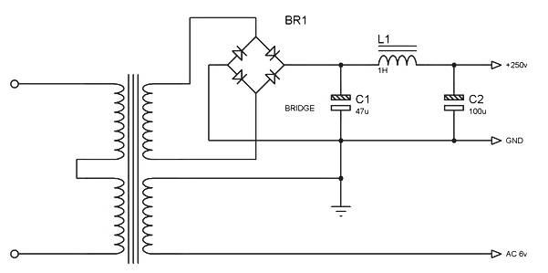
Power supply for a simple high-quality tube amplifier class A power supply. This power supply circuit is part of a series of simple high-quality tube amplifier class "A" designs. It may also be applicable to other devices. Detailed explanation:...
The circuit involves infrared phototransistor pairs positioned at three locations within a maze, including the endpoint. The maze is designed to be narrow enough for a single finger to slide through, and as fingers pass the phototransistors, a sound...
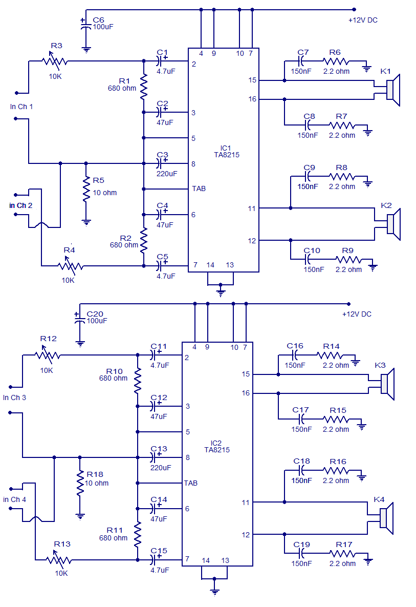
Many electronic circuits related to audio amplifiers have been published. This particular circuit is unique as it is a four-channel amplifier. Each channel can deliver an output of 15 watts into a 4-ohm speaker. The amplifier operates from a...