
Arduino Punk Console

The circuit design for the programmable 8 step tone sequencer based on an Arduino microcontroller incorporates several key components that work together to produce a series of tones in a sequenced manner. The primary component is the Arduino microcontroller, which serves as the brain of the operation, controlling the timing and output of the tones.
The sequencer is designed to allow user programming of up to 8 distinct steps, with each step capable of defining a specific tone frequency and duration. The Arduino can be programmed using the Arduino IDE, allowing for easy modifications and updates to the tone sequences.
An essential feature of this circuit is the inclusion of a 2 line x 16 character backlit LCD display. This display provides a user interface for programming the sequencer, allowing users to view and edit the sequence parameters such as tone frequency, duration, and the overall sequence length. The LCD is connected to the Arduino via an I2C interface, which simplifies wiring and reduces the number of required pins.
In addition to the microcontroller and LCD, the circuit includes a piezo buzzer or speaker, which serves as the output device for the generated tones. The audio output can be amplified using a simple transistor amplifier circuit, ensuring that the tones are audible even in noisy environments.
Powering the circuit can be achieved through a standard USB connection or an external power supply, depending on the application requirements. Proper voltage regulation and decoupling capacitors should be included to ensure stable operation of the microcontroller and other components.
Overall, this programmable 8 step tone sequencer offers a versatile platform for creating sound sequences, suitable for applications in music, alerts, or other audio signaling needs.A programmable 8 step tone sequencer using an Arduino microcontroller. Features a 2 line x 16 character backlit LCD display 🔗 External reference
Related Circuits
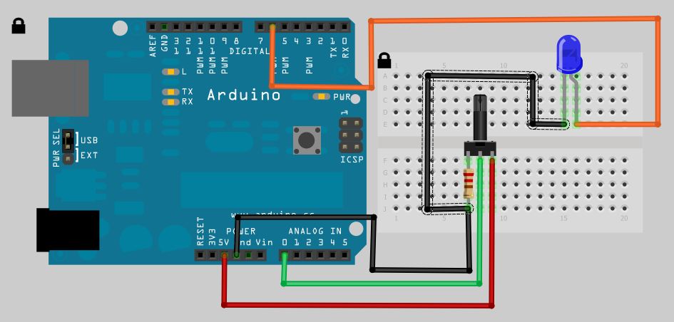
The analog to digital sketches have been extensively covered using various components. To progress to more complex circuits and concepts, it is essential to understand these simpler ones. This tutorial will not delve as deeply as others due to...
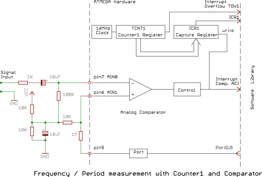
Software on a MacBook Pro includes Laidman & Katsura's WaveWindow, which functions as a software oscilloscope. It is beneficial for individuals working with sound on the Mac, offering an educational and entertaining experience. Additionally, Faberacoustical's Signal Scope allows for...
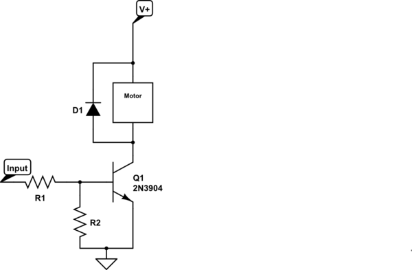
Control a small 5V motor using an external power supply by triggering a transistor with an Arduino. The transistor in use is an NPN type, specifically the 2N3904. To control a small 5V motor using an Arduino and an NPN...
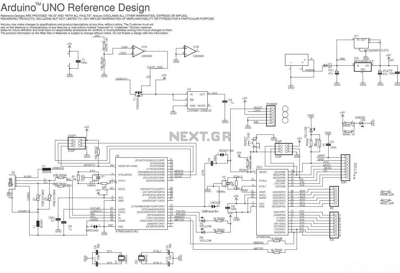
The Arduino Uno schematic diagram is available for viewing. The Arduino Uno is a microcontroller board that utilizes the ATmega328 chip. It features 14 digital input/output pins, of which 6 can be used as PWM outputs, and 6 analog...
The Arduino microcontroller board can supply a current of 40mA from its output connections, with digital outputs fixed at 5V for "ON" and 0V for "OFF." This current is suitable for LEDs, but devices like motors, solenoids, and high-brightness...
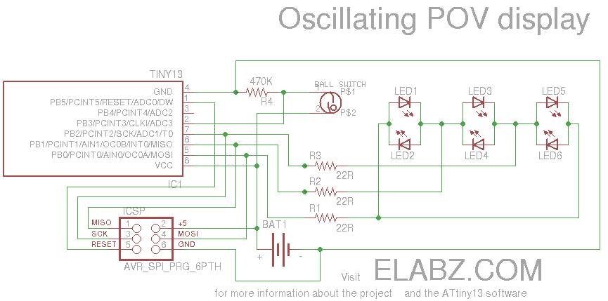
Smart Valentine's Day gift - a movement-sensing box of chocolates with an LED message. Circuit diagram and instructions for building the project using ATtiny13 and Arduino. The project involves creating a movement-sensing box of chocolates that incorporates an LED display...