
arduino serial thermometer

The circuit utilizes an Arduino microcontroller along with an MCP9700 temperature sensor integrated circuit (IC) to measure ambient temperature. The MCP9700 operates within a voltage range of 2.7V to 5.5V and outputs an analog voltage that is linearly proportional to the temperature, with a scale factor of 19.5 mV/°C.
In this configuration, the MCP9700 is connected to one of the analog input pins of the Arduino. The output pin of the MCP9700 is connected to an analog input pin, typically labeled A0 on the Arduino board. A power supply connection is established by connecting the VDD pin of the MCP9700 to the Arduino's 5V output and the GND pin to the common ground.
The Arduino is programmed to read the analog voltage output from the MCP9700. This voltage is converted into a temperature reading using the formula:
Temperature (°C) = (Analog Read Value * 5V / 1024 - 0.5) / 0.0195
The calculated temperature is then displayed in the Arduino IDE's serial monitor, providing real-time temperature readings. The code structure includes initializing the serial communication in the setup function and continuously reading the analog input in the loop function, followed by the conversion of the analog value to temperature and outputting the result to the serial monitor.
This setup is suitable for various applications, including environmental monitoring, weather stations, and educational projects to demonstrate temperature sensing and data acquisition using microcontrollers.The Arduino reads temperature from a MCP9700 temperature sensor IC and displays the temperature in the Arduino IDE serial monitor window.. 🔗 External reference
Related Circuits
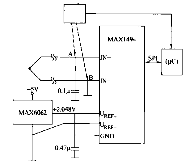
The circuit consists of the MAX1494 and a thermocouple temperature measurement system. The MAX1494 is terminated at 1N GND 5-32. An external temperature sensor, such as the DS75, can be utilized for junction temperature compensation. The MAX1494 employs an...
Create a USB to Serial Converter using the ATmega8 microcontroller. The firmware source code for the ATmega8 is available for free download. Since the ATmega8 does not natively support USB communication, the USB communication protocol must be implemented within...
Here is an inexpensive way to get slow-moving analog data directly into a spreadsheet on your computer! A simple circuit connects to a serial port and a short Qbasic program gathers and saves 12 bit data to a file....
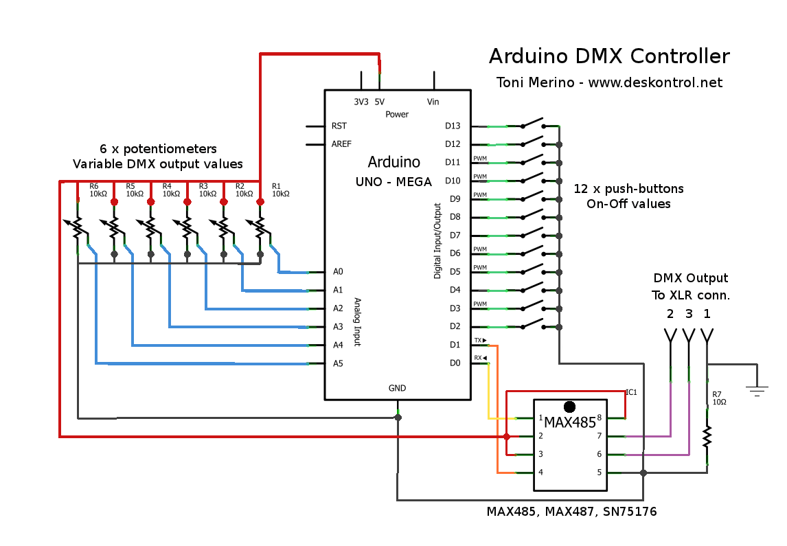
This document outlines the process of creating a compact and efficient Arduino DMX512 controller, which can be utilized to operate devices like a smoke machine via DMX or serve as testing equipment. The configuration includes six channels controlled by...
DAC stands for Digital to Analog Converter. This article explores the code created by Michael Smith for a PWM-based DAC. The code has been modified to allow for the testing of various DAC options. A comparison is made between...
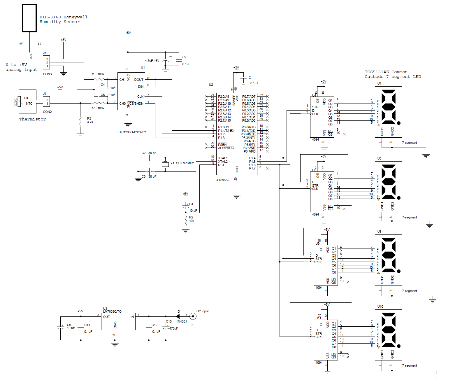
This circuit features a microcontroller AT89S52 thermometer paired with an LTC1298 12-bit ADC. The program is written in C language and incorporates digital filtering along with an interface for an LED display. The temperature readings have a sensitivity of...