
Thermocouple thermometer circuit

The circuit design integrates the MAX1494, a precision analog front-end device, specifically tailored for thermocouple applications. It is responsible for converting the small voltage generated by the thermocouple into a digital signal that can be processed by a microcontroller or other digital systems. The termination at 1N GND 5-32 indicates the grounding scheme utilized, which is crucial for maintaining signal integrity and minimizing noise in the system.
In this setup, the DS75 external temperature sensor plays a vital role in providing accurate temperature readings. It can be interfaced with the MAX1494 to perform junction temperature compensation, ensuring that the temperature measurements reflect the actual conditions of the thermocouple junction. This compensation is essential for applications requiring high accuracy, as it accounts for any temperature differences that may affect the measurement accuracy.
The MAX6062 voltage reference is used to provide a stable reference voltage of +2.048V to the MAX1494. This external reference is critical for the performance of the MAX1494, as it ensures that the analog-to-digital conversion process is consistent and reliable, minimizing drift and enhancing the overall precision of the temperature measurements.
Overall, this combination of components creates a robust and accurate temperature measurement system suitable for various industrial and scientific applications, where precise temperature monitoring is essential.Circuit from the MAX1494 and thermocouple temperature measurement system as shown, MAX1494 termination of 1N GND 5-32. The use of an external temperature sensor (for example, DS75) and SCM can be done carry junction temperature compensation work.
MAX1494 uses an external reference provided by the MAX6062 reference voltage +2. 048V is.
Related Circuits
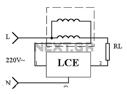
This is an application circuit of the device as illustrated in principle. In the meter, the voltage and current coils are connected to the power line, regardless of whether a load is connected. The voltage coil consistently draws power,...
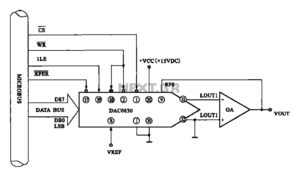
Figure 8 illustrates a typical digital-to-analog (D/A) conversion circuit that utilizes the DAC0830/DAC0832 chip. The microprocessor outputs an 8-bit digital signal, which is converted into an analog signal. The D/A conversion circuit depicted employs the DAC0830/DAC0832, which is a dual...

This circuit utilizes the TA7222AP to amplify audio signals. The cost is only $0.99, and it can provide 5.8 watts with muting control. The power supply can be in the range of 8-12 VDC, making it suitable for applications...
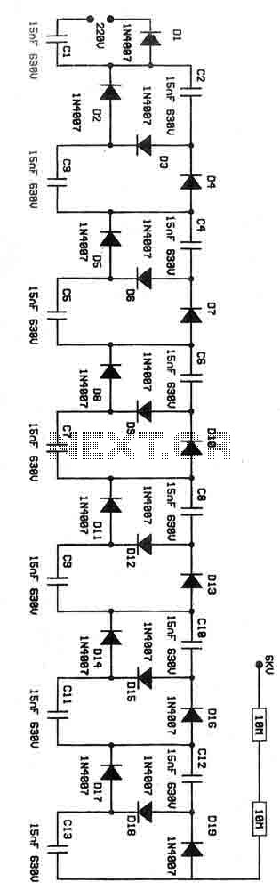
This is a voltage multiplier circuit functioning as an ionizer. It is designed to convert 220V from the mains supply into an output of approximately 6kV. Caution is advised when handling this circuit due to the potential dangers associated...
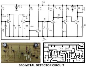
Metal Detector Circuit Overview The metal detector circuit is an electronic circuit that is specifically designed to detect metal that lies deep in the water. The metal detector circuit operates on the principle of electromagnetic induction, where a coil generates...

Metal detector schematic circuit using CS209A and a few electronic components. The metal detector circuit utilizing the CS209A integrated circuit is designed to detect metallic objects through the principle of electromagnetic induction. The CS209A is a specialized IC that facilitates...