
Arduino Tone 3

The circuit design encompasses the use of three force-sensitive resistors (FSRs) connected in parallel to a 5V power supply. Each FSR serves as an analog sensor, allowing for the detection of varying pressure levels that can be translated into musical notes.
To implement this circuit, each FSR is connected to one of the analog input pins on a microcontroller, specifically pins A0, A1, and A2. The configuration ensures that the sensors can be read simultaneously, providing real-time feedback on the pressure applied to each FSR. A 10K ohm resistor is connected from each analog pin to ground, establishing a voltage divider configuration that allows for accurate readings of the analog voltage corresponding to the resistance of the FSR. This setup is crucial for ensuring that the microcontroller can interpret the varying resistance of the sensors as voltage levels.
The microcontroller is programmed to read the analog values from the three sensors. The readings are then compared against predetermined threshold values. If the voltage from any sensor exceeds its respective threshold, the microcontroller triggers the playback of a specific note from an array of notes. This array can be predefined in the code, allowing for flexibility in the musical output based on the pressure detected by the FSRs.
This configuration is particularly useful in interactive applications where physical input can influence sound generation, making it suitable for musical instruments, educational tools, or interactive installations. The careful selection of resistor values, sensor types, and microcontroller programming ensures reliable performance and responsiveness in detecting user input.Power your three FSRs (or any other analog sensor) with 5V in parallel. Connect each sensor to analog pins 0-2, using a 10K resistor as a reference to groud on each input line. The sketch below reads three analog sensors. Each corresponds to a note value in an array of notes. IF any of the sensors is above a given threshold, the corresponding note is played. 🔗 External reference
Related Circuits
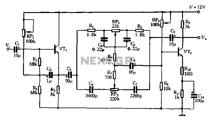
The attenuation circuit is a feedback tone control system that consists of transistors and an RC network. The circuit includes a low tone control potentiometer (RP2) and a treble control potentiometer (RP3). The bass control is influenced by resistor...
This circuit features a two-tone siren integrated within a single IC. It is designed for children's entertainment and can be installed on bicycles, car battery chargers, and other applications. The two-tone siren circuit utilizes a single integrated circuit (IC) to...
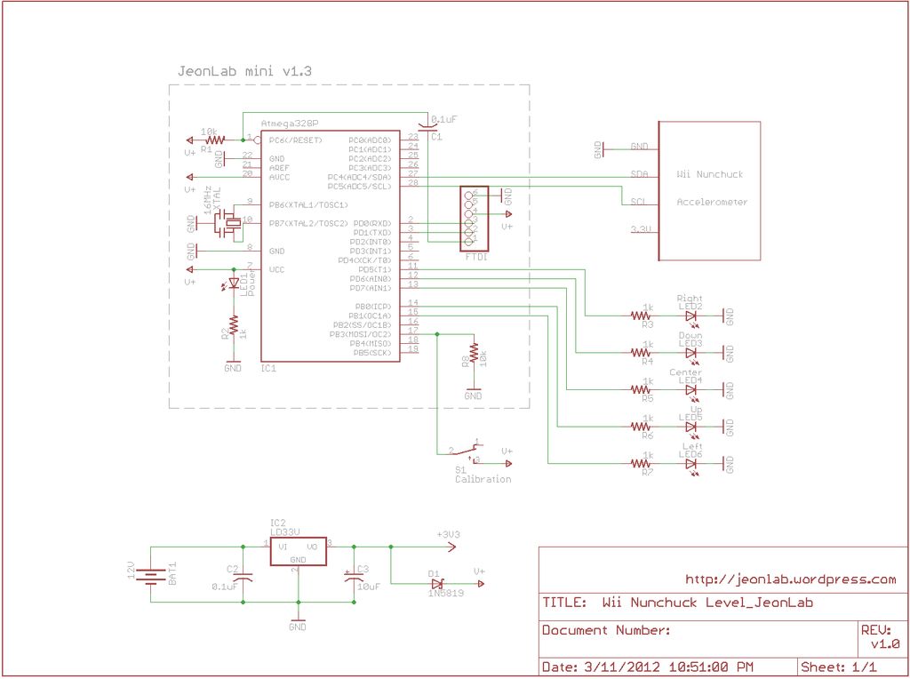
After reading an article on the Todbot blog, a purchase was made for several Wii Nunchucks from eBay. The exact amount paid is not recalled, but it was significant. The Wii Nunchuck is a motion-sensing input device that connects to...
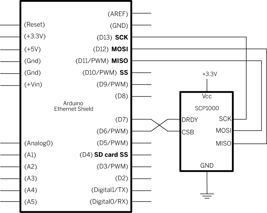
This example demonstrates how to utilize SPI communication to read data from an SCP1000 Barometric Pressure sensor and subsequently transmit that data to the web using an Arduino and Ethernet Shield combination as a simple web server. By employing...

This circuit is capable of generating up to 1 W of audio power to drive a speaker or horn. When the CDS cell is exposed to light, its resistance decreases, activating NOR gate (a). This activation causes gates (a)...
The crock pot is connected to a relay that can turn it on or off. The relay is controlled by a microcontroller based on readings from a temperature sensor (thermistor) located inside the crock pot. The objective is to...