
Astable multivibrator

In this circuit configuration, a capacitor (C) is utilized to store electrical energy, which is managed through two resistors (Ra and Rb). During the charging phase, the capacitor receives current through both resistors, Ra and Rb, thereby influencing the time it takes to reach its maximum voltage. The values of these resistors play a crucial role in determining the charging rate, as the time constant (τ) of the RC circuit is defined by the equation τ = R_total × C, where R_total is the equivalent resistance seen by the capacitor during charging.
Once the capacitor is fully charged, it enters the discharging phase, where it releases its stored energy solely through resistor Rb. This configuration allows for a distinct control over the discharge time, as the discharge time constant is given by τ_d = Rb × C. The ability to adjust the values of Ra and Rb provides flexibility in managing the duty cycle of the circuit, which is the ratio of the time the capacitor spends in the charging phase to the total period of the cycle. By changing the resistance values, one can effectively modify the duration of both charging and discharging intervals, thus tailoring the performance characteristics of the circuit for specific applications, such as timing circuits, pulse generators, or signal modulation systems.
This circuit can be employed in various electronic applications where precise timing and control are essential, such as in oscillators, timers, or as part of more complex signal processing systems. The design considerations should include the selection of capacitor and resistor values that meet the desired frequency response and duty cycle requirements.The capacitor C will charge through Ra and Rb, and then discharge through Rb only The duty cycle may be controlled by the values of Ra and Rb.
Related Circuits
A monostable multivibrator using the IC CD4538 is a precision device that functions as a monostable/astable multivibrator and is designed to avoid false triggering. This IC is suitable for various applications requiring precise timing cycles. The CD4538 offers improved...
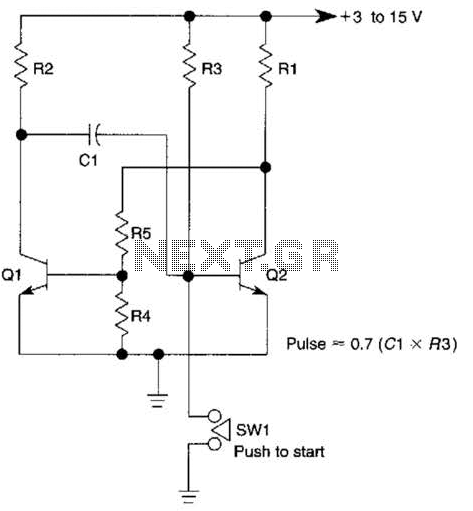
This circuit is activated when switch SW1 is pressed, grounding the base of transistor Q2. The pulse rate is approximately equal to 0.7 multiplied by the product of resistor R3 and capacitor C1. The described circuit features a transistor Q2,...
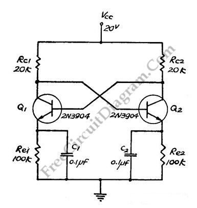
This flip-flop circuit functions as a free-running astable multivibrator, where the bases and collectors of both emitter-biased transistors are directly coupled. The switching action is facilitated by a capacitor in each emitter circuit, resulting in the generation of triangle...

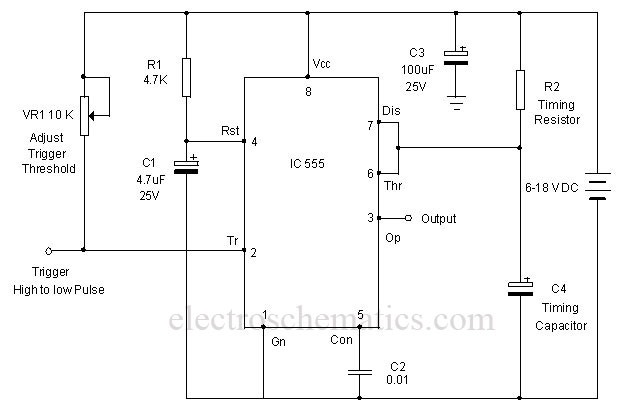
The 555 is a highly stable device for generating accurate time delays or oscillation. Additional terminals are provided for triggering or resetting if desired. In the time delay (monostable) mode of operation, the time is precisely controlled by one...
A one-shot multivibrator circuit, commonly referred to as a monostable multivibrator or timer, is designed to generate a pulse strobe of fixed duration in response to an input trigger. The one-shot multivibrator is a fundamental circuit used in various electronic...

This plugin features a single 555 timer in astable mode. It is highly versatile and can be utilized for various applications, commonly serving as a clock signal generator for circuits. The configuration described produces a pulse frequency of approximately...