
Astable

The 555 timer in astable mode operates continuously, generating a square wave output that can be used for timing applications, pulse generation, or clock signals. In this configuration, the timer alternates between high and low states, creating a periodic output. The frequency and duty cycle of the output waveform can be adjusted by selecting appropriate resistor and capacitor values connected to the timer.
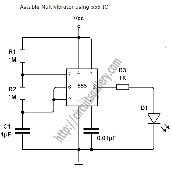
In the astable mode, two resistors (R1 and R2) and a capacitor (C1) are critical components. The resistors determine the charge and discharge times of the capacitor, which in turn sets the frequency of the output signal. The formula for the frequency (f) of the output waveform is given by:
f = 1.44 / ((R1 + 2 * R2) * C1)
The duty cycle, which indicates the proportion of time the output is high versus low, can be calculated using the following formula:
Duty Cycle (%) = (R2 / (R1 + 2 * R2)) * 100
In this specific implementation, the low mark-space ratio indicates that the output signal remains low for a longer duration compared to its high state. This characteristic can be beneficial for applications requiring a slower clock signal or for driving components that require limited activation time.
The output from the 555 timer can be connected to various loads, including LEDs, transistors, or other logic circuits, depending on the desired application. Proper decoupling capacitors should be used near the power supply pins of the 555 timer to ensure stable operation and minimize noise.
Overall, the 555 timer in astable mode is a fundamental building block in electronics, widely used for generating clock pulses and timing signals across various applications.This plugin consists of a single 555 Astable. This plugin is very versatile, and can be used for any number of things, but it often is used to give a clock to run a circuit. The plugin below gives a pulse of about 2Hz with a very low mark-space ratio. The circuit diagram is given below. 🔗 External reference
Related Circuits
Simulation schematic for an astable multivibrator. Parameters: Vcc = 24V, Vol = 1V, Voh = 21V. The power supply is Vcc, with connections from Vcc to ground. The time constant is determined by R1 and the capacitor C1, where...
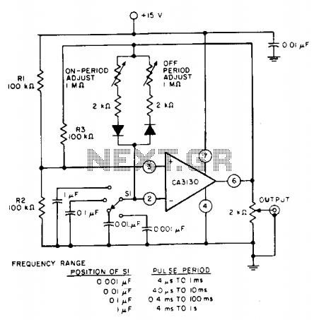
The pulse repetition rate is determined by adjusting switch SI to the desired position, and this rate remains relatively constant even when the resistors that control the on-period and off-period are modified. Resistors R1 and R2 set the biasing...
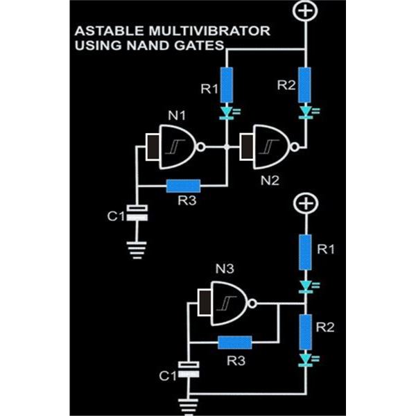
An astable multivibrator is an electronic configuration that generates continuous alternating high and low pulses from two outputs operating in tandem. The IC 4093 consists of four individual NAND gates in one package, specifically Schmitt trigger types, which provide...
What exactly is a multivibrator? I suppose one definition would be 'a circuit which has several states'. This will do for now, it's quite loose so leaves plenty to the imagination! Conventional multivibrators have only two stages and come...
An astable multivibrator can be designed using a 555 timer IC, operational amplifiers, or transistors. The 555 timer IC provides accurate time delays ranging from milliseconds to hours, with the frequency of oscillation adjustable through simple modifications. This is...
The circuit illustrated is a straightforward digital frequency meter that displays the frequency in hertz of an astable 555 timer. It may potentially be modified for alternative applications. An NPN transistor, TR2, is linked to the 555 astable timer...