
Astable Multivibrator

The astable multivibrator circuit is a fundamental application of bipolar junction transistors (BJTs) configured to produce a continuous square wave output. This circuit does not have a stable state; instead, it oscillates between two unstable states, which results in the alternation of LED illumination.
In this configuration, two NPN transistors are used, each connected to a resistor-capacitor (RC) timing network. The timing network consists of two resistors and two capacitors, with each transistor controlling one LED. The charging and discharging cycle of the capacitors through the resistors determines the oscillation frequency. When one transistor turns on, it allows current to flow through its associated LED, causing it to light up, while simultaneously turning off the other transistor and extinguishing its LED.
The choice of a 470-ohm collector load resistor is crucial as it sets the maximum current flowing through the LEDs, ensuring they operate within safe limits without being damaged. The 20-milliamp current is suitable for standard 5mm LEDs, providing adequate brightness without overheating.
The frequency of oscillation can be adjusted by varying the values of the resistors and capacitors in the circuit. Using smaller resistor values or capacitors will result in a higher frequency, allowing for more rapid alternation between the two LEDs. This feature enables customization of the flashing rate to suit specific application requirements.
For applications requiring different brightness levels or color combinations, various types of LEDs can be used, and they can be wired in series with the collector resistors. Additionally, different transistor types can be selected based on the desired switching speed and current handling capabilities, which can further enhance the circuit's performance. This flexibility makes the astable multivibrator circuit a versatile choice for LED flashing applications in various electronic projects.This is an Astable Multivibrator Circuit to alternately flash two LEDs. The R and C Values determine the frequency and the 470 ohm collector load resistors set the current to about 20 miliamp, when the circuit is operated at 12Volts. Frequncy is about 1Cylce per second using 22uF capacitors and 47K resistors. Smaller R and C Values will increace Freq uency. The LEDs may also be wired in series with the collector resistors and other transistors can be used. 🔗 External reference
Related Circuits
This circuit is basically simple and easy to build, it uses two transistors as active components and a few passive components like resistors, capacitors and two LEDs. The circuit makes use of the MPS2222 transistor. You can use any...
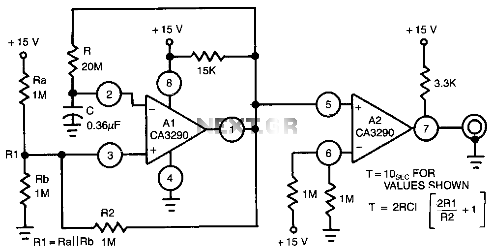
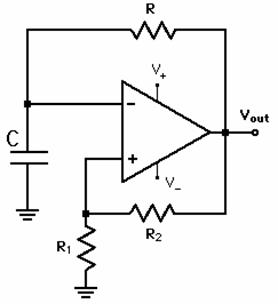
This circuit utilizes one half of the CA3290 BiMOS dual voltage comparator as a conventional multivibrator. The second half ensures frequency stability against the effects of output loading. Large values of the timing resistor, Rl, guarantee long time delays...
An astable multivibrator needs to be designed, and the maximum and minimum frequencies generated at the output must be calculated. An astable multivibrator is a type of oscillator circuit that continuously switches between its high and low states without requiring...

For the time it takes to charge to 0.6V, the other capacitor has already charged significantly (a value that cannot be determined because the setup does not function until one of the two states—Q1 is on or Q2 is...
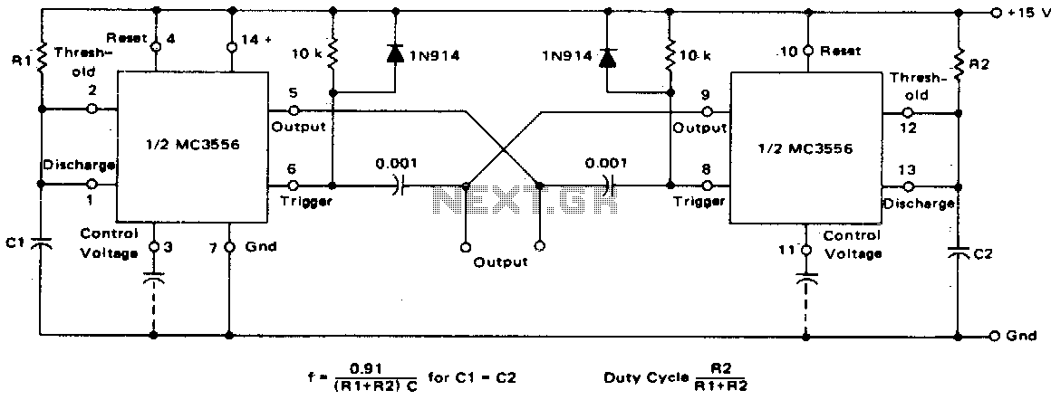
This dual astable multivibrator offers versatility not found in single timer circuits. The duty cycle can be adjusted from 5% to 95%. The two outputs generate two-phase clock signals, which are frequently required in digital systems. Additionally, it can...
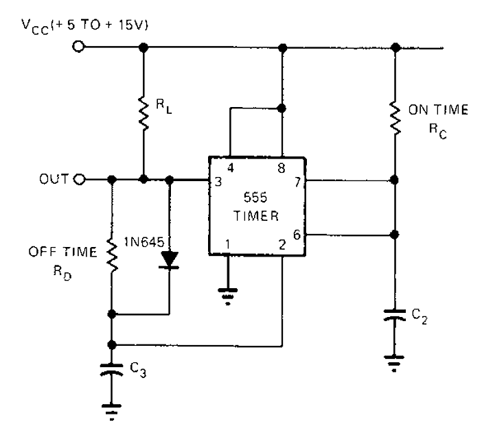
The 555 timer circuit has unsteady open and closing times that are independent of one another. One time constant is given by 1.1RcC2, while another time constant is defined as 1.1RcC3. The free-running period is the sum of these...