
Astable Multivibrator Electronic

The described circuit functions either to trigger a connected device or to operate in a free-running mode, depending on the configuration of the components involved. The primary components include a battery for power supply, a charger for recharging the battery, and a battery connector that facilitates the connection between the battery and the rest of the circuit.
In addition, a capacitor is present, which may be utilized for filtering or energy storage purposes, ensuring stable operation of the circuit. The integrated circuit (IC) serves as the control unit, managing the triggering mechanism or the free-running operation.
Resistors VR1 (10K ohm), R1 (1K ohm), and R2 are integral to the circuit's operation. Resistor VR1 is likely a variable resistor, allowing for adjustable resistance, which can be used to fine-tune the circuit's response or timing characteristics. Resistor R1 may be involved in setting the biasing conditions for the IC, while R2 could play a role in current limiting or voltage division within the circuit.
Overall, this schematic provides a versatile platform for triggering devices or operating continuously, making it suitable for various applications in electronics, including timers, oscillators, or control systems. The precise arrangement and values of the components will determine the specific behavior and performance of the circuit.Function: to trigerred device or freerunning. Component: Battery, Charger, Battery Connector, Capacitor, IC, Resistor VR1-10K, Resistor R1-1K, Resistor R2 .. 🔗 External reference
Related Circuits
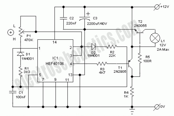
This electronic lighting dimmer circuit is designed to control the brightness of incandescent lamps, but it is not suitable for fluorescent lamps. It operates with both 110V and 220V AC power sources. The circuit is connected in series with...
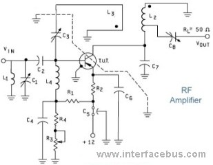
The allowable reduction in system performance. For a fire control radar, the acceptable degradation is usually expressed as a reduction in range; for example, the maximum lock-on range might be degraded by 25 percent without loss of essential defense...
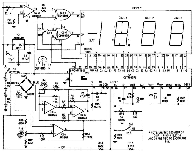
An electronic scale utilizes a pressure transducer (load cell) along with an analog-to-digital (A/D) converter to operate a digital display. The scale's range is determined by the specifications of the load cell, and the display is calibrated in suitable...

Automatic electronic refrigerator deodorant sterilization circuit The automatic electronic refrigerator deodorant sterilization circuit is designed to eliminate odors and sterilize the interior of a refrigerator. This circuit typically employs a combination of sensors, microcontrollers, and sterilization techniques to achieve effective...
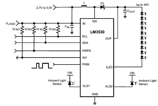
A simple white LED driver circuit can be designed using the LM3530 high-efficiency white LED driver IC, which features programmable ambient light sensing capability and an I2C compatible interface. The LM3530 LED driver can control up to 11 series...
This circuit is very basic to build. To open a the lock which is connected to the K1 Load you must press each momentary switch in the correct sequence. The sequence used in this circuit is S1, S2, S3,...