
Electronic Lamp Dimmer Circuit

This electronic lighting dimmer circuit utilizes a triac-based design to adjust the brightness of incandescent lamps. The circuit's operation hinges on the charging and discharging characteristics of capacitor C4, which is influenced by the resistors R3, R4, P1 (the potentiometer), and R5. The potentiometer allows for user adjustment of the charge time, thus controlling the brightness level.
When the circuit is powered, C4 begins charging through the resistors. Once the voltage across C4 reaches a threshold level, diac D switches on, allowing current to flow to the gate of the triac. The triac then turns on, enabling power to the lamp. The absence of a switch in the circuit necessitates careful handling to prevent electric shock, particularly since the dimmer is not isolated from the AC mains.
For added safety, the inclusion of a fuse is crucial, as it protects against overcurrent conditions. The design allows for the installation of an additional switch if desired, which can provide a convenient means of turning the lamp on and off without needing to adjust the dimmer setting. It is also vital to ensure that the total wattage of lamps connected to the dimmer does not exceed its rated capacity, as this could lead to overheating and potential failure of the circuit. Users should verify the wattage ratings of their bulbs, ensuring they remain within the operational limits of the dimmer to maintain safe and effective functionality.This electronic lighting dimmer circuit is used to control the lamp for arbitrary brightness. This electronic lamp dimmer circuit work for incandescent lamp, not a fluorescent one. The dimmer circuit here work for both 110V and 220V AC. The dimmer circuit is wired in series with the lamp, you can say the dimmer circuits is installed in series with the lamp. Be careful that the circuit is not isolated from high voltage, so the potentiometer should be installed with plastic knob. Don`t touch the circuit or you`ll be shocked by the electricity. The lamp dimmer has no switch, you can see only a fuse for safety. You can add a switch in series with the fuse, or just insert this dimmer circuit between the existing swith and the lamp.
Capacitor C4 is charged via resistors R3, R4, P1, and R5. After a certain time, dependant on the potentiometer, the charge contained in C4 is large enough for diac D to start conducting, so that a firing pulse is applied to the gate of the triac. Consequently the triac conducts and power is transferred to the lamp. Be aware that dimmer switches can only handle a specific amount of light load. You can typically purchase dimmers that are rated for 600 or up to 1, 000 watts of lighting. Light bulbs are usually clearly marked as to their wattage. Determine the total wattage of the bulbs that are being controlled by any one dimmer. 🔗 External reference
Related Circuits
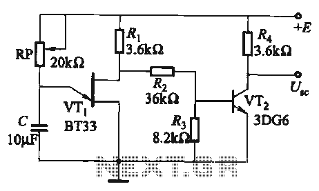
The circuit comprises a single-junction transistor VTi, a resistance Ri, a potentiometer RP, and a capacitor C, forming a relaxation oscillator and an amplifier transistor VTz. The adjustment potentiometer RP allows for changing the relaxation oscillation frequency, providing a...
Here is a circuit for using the printer port of a PC, for control application using software and some interface hardware. The interface circuit along with the given software can be used with the printer port of any PC...
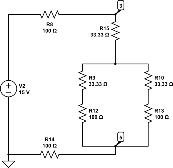
The Delta configuration of resistors R2, R3, and R4 is converted to a Wye (Y) configuration. This conversion is necessary because a voltage divider is typically employed in series circuits. The aim is to determine the total resistance in...
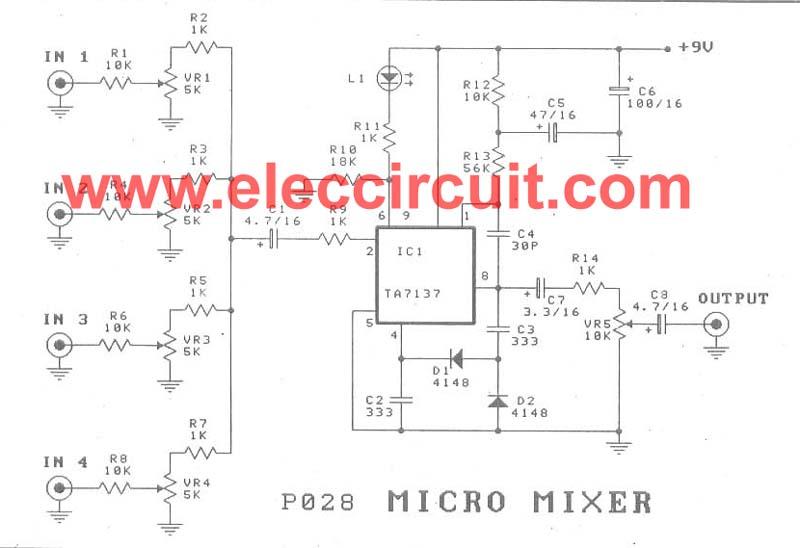
A micro mixer circuit is designed to be simple, affordable, compact, and versatile. This circuit can mix up to four input channels, including microphone signals, FM tuners, AUX, and other signals, as illustrated in Figure 1. The operation begins...
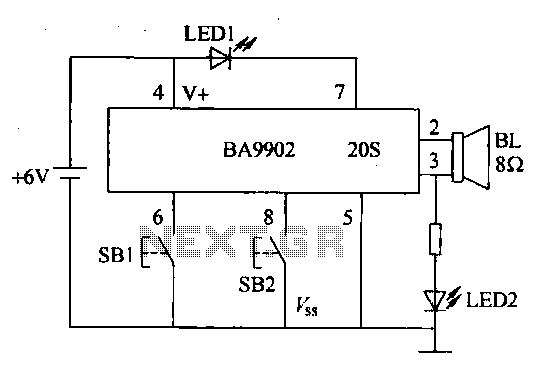
The voice recorder's entry information can be stored for 100 years, repeated 100,000 times, with low power consumption. It requires a 5-6V DC power supply and has a recording current of 2 mA. The voice recorder circuit is designed to...
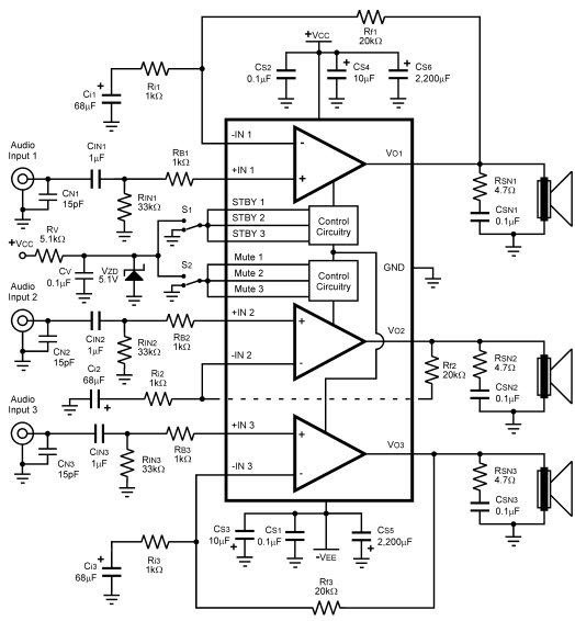
The LM4782 utilizes a protection system known as National Self Peak Instantaneous Temperature (Ke) (SPiKeTM). SPiKe safeguards the output of the LM4782 against over-voltage on the load, short circuits to ground, and provides temperature protection by monitoring instantaneous temperature....