
Astable multivibrator in an 8 pin PIC

The envisioned circuit for the Xbox controller rapid fire modification can be implemented using a microcontroller that is capable of handling the required inputs and outputs effectively. The microcontroller should have at least two general-purpose input/output (GPIO) pins to control the switches and additional pins to manage the trigger signals. The selection of a microcontroller such as the PIC10F200 is appropriate due to its compact size and affordability, making it suitable for small-scale applications like this modification.
The design will require a power supply circuit that connects the 5-volt source to the microcontroller, ensuring stable operation. The ground signal will be routed through the microcontroller to generate the rapid fire effect. The programming of the microcontroller will involve writing firmware that can toggle the GPIO pins at a high frequency, giving the impression of a rapid fire function when activated.
The output from the microcontroller will be connected to the two switches, which will be integrated into the Xbox controller's circuitry. The left and right trigger connections will also be managed by the microcontroller to ensure that the rapid fire mod operates seamlessly with the controller's existing functionality.
In terms of programming, a suitable programmer should be acquired to upload the firmware to the microcontroller. Options for programmers include the ICD2 for serious development or a more budget-friendly option like the Velleman K8048, which provides a learning opportunity for those new to programming microcontrollers. The firmware can be developed using an Integrated Development Environment (IDE) compatible with the chosen microcontroller, allowing for code simulation and debugging before deployment.
Overall, this modification project is feasible with the right components and programming knowledge, and it can enhance the functionality of the Xbox controller by implementing a rapid fire feature.Xbox controller, a rapid fire mod. All it has to do is send a ground signal to one spot really fast. I make this schematic and sell it(an of course use it): What I need is a chip that thinks that that schematic is in it. Dont suggest a 555 timer, because when I made that it was big, too big. I used this schematic for the 555 timer: So, can I program a chip for the first schematic Or even better, you help me(I mean you do it) Or can it even be done For inputs it would get a ground, and 5 volt. For output it would need 2 switches, so four leads, and 2 other wires(left trigger and right trigger).
I dont think this can be done, but I no nothing about programing. Thanks for any help. So, can I program a chip for the first schematic Or even better, you help me(I mean you do it) Or can it even be done For inputs it would get a ground, and 5 volt. For output it would need 2 switches, so four leads, and 2 other wires(left trigger and right trigger).
I dont think this can be done, but I no nothing about programing. Hi. Yes of course this can be done, but I`m not sure what you are asking of this forum. Is it that you want some one here to write a program for you intended application. Or you just want to know what microcontoller would be best for your application. If this is the case. I suggest you look at the 16f628(a). It is a popular device for small/medium applications like the one you`ve posted and it is basically a superseded device of the ever ex-popular 16f84/a where you will still find much learning material about. I hope this helps. Regards. Violin. Hello. I have no idea at all about programming chips. I am good with building stuff though, not programming. I want to program a chip for my Xbox controller, a rapid fire mod. All it has to do is send a ground signal to one spot really fast. I make this schematic and sell it(an of course use it): What I need is a chip that thinks that that schematic is in it.
Dont suggest a 555 timer, because when I made that it was big, too big. I used this schematic for the 555 timer: I`m sort of confused - I think you`ve got an error in your 555 schematic. in your discrete transisor schematic, you show both triggers coming off the transistor collectors. For the 555 version, the left trigger is coming off of the emitter. So, can I program a chip for the first schematic Or even better, you help me(I mean you do it) Or can it even be done For inputs it would get a ground, and 5 volt.
For output it would need 2 switches, so four leads, and 2 other wires(left trigger and right trigger). I dont think this can be done, but I no nothing about programing. Thanks for any help. This looks like the perfect application for a 6-pin PIC10 series, for the ultimate in low size and cost.
A PIC10F200 is about $0. 39 in large qty, and about $0. 50 in lower quantities. The 555 timer schematic wasnt made by me, I just put it on my site for reference. I made it and it worked fine, but I didnt use it long and for all I know it could have been causing damage. Thanks for the fast help. Where can I get a programer Could I build my own programer(not the software, hardware). Hi. Although ICD2 is the preferred programmer here by most. Myself included. It is not a cheap priced programmer. It is a Mid-ranged price programmer. However, if you do purchase one, you will probably be happy to stick with it forever. Ok. If you want to start off with a cheap one just to get the feel of the programming world. The Velleman K8048 may interest you. It comes in kit form. So is a great learning tool for the workings of a programmer and have footprints for 8/14/18 and 28pins microcontrollers and ICSP for the 40pin 16f877 can`t remember if the (a) one is included.
That will need to be checked on. Although it doesn`t support a great number of 🔗 External reference
Related Circuits
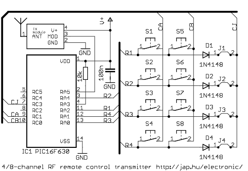
This is a general purpose remote control project with using programmable PIC microcontrollers. Schematics are shown for using infrared (RF) or radio (RF) media. If you are not familiar with microcontroller programming, you can use fixed encoder and decoder...
Over the weekend, an attempt was made to perform mechanical work by machining acrylic material to create a joint using a stepper motor. The effort was unsuccessful, particularly when trying to score and snap the acrylic, as cutting lengths...
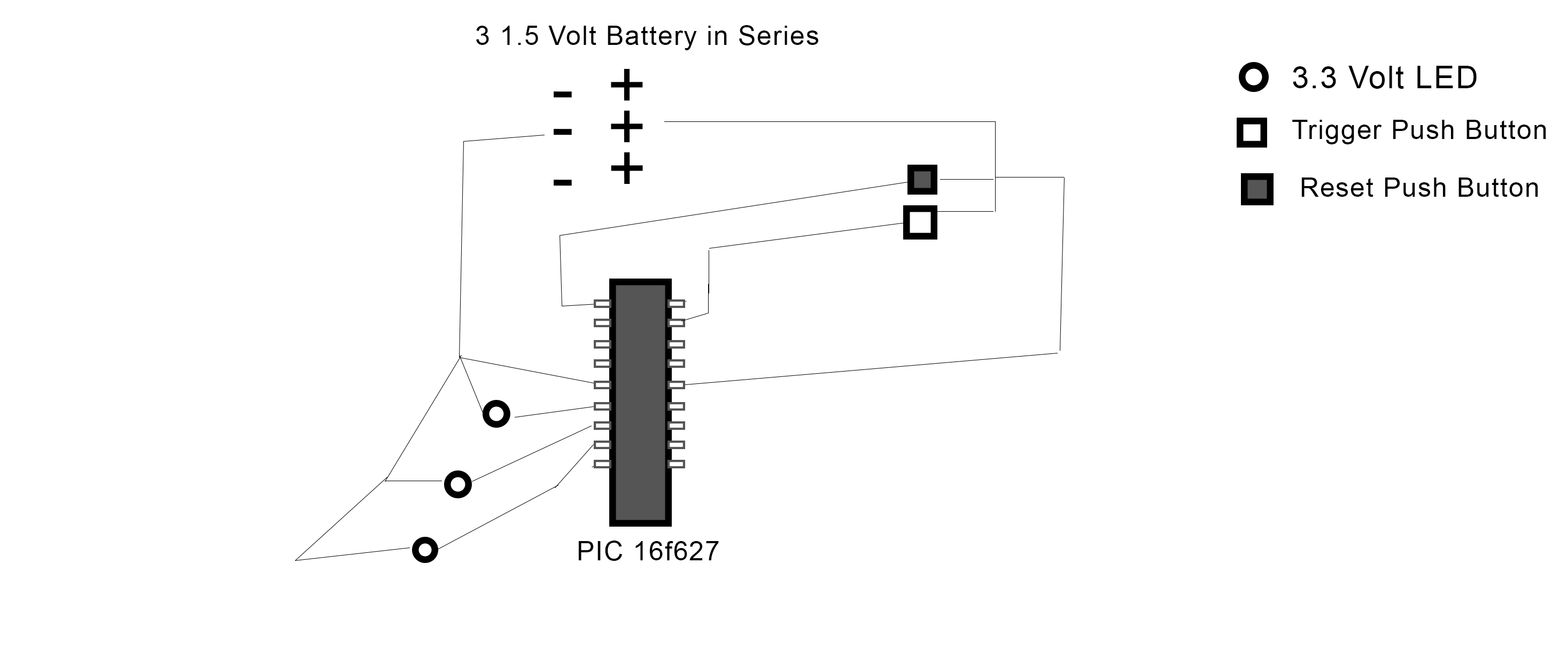
The PIC 16F627 microcontroller has been programmed to activate three LEDs when a trigger pushbutton is pressed. Additionally, when a reset pushbutton is pressed, a shutdown sequence is initiated where each LED turns off sequentially with a 5-second delay...

The figure illustrates a circuit involving dark tomb electric locks, specifically the fti: al: 4046B and XOR gate as the primary control mechanism. It emits pulses and utilizes silicon for successive pulse generation. The circuit operates with a normal...
This device uses a PIC12F615 to implement a capacitor discharge ignition system. When the switch (button) is closed, the PIC sends pulses to the IRF644 MosFet creating high voltage pulses to charge the 1.0 uf/250 volt capacitor. The voltage...
A circuit is being designed to drive a 4x7 segment display using a PIC microcontroller. The previous implementation utilized four pins to control each of the four digits individually, with a sequential activation method. The designer aims to simplify...