
Astable Multivibrator with 2 Transistors

The circuit operates by leveraging the characteristics of NPN transistors, specifically the MPS2222, which is known for its reliability and efficiency in switching applications. The primary function of this circuit is to control the on/off state of the two LEDs based on the input signal applied to the base of the transistors.
In this configuration, the first transistor acts as a switch that controls the second transistor. When a sufficient voltage is applied to the base of the first transistor, it allows current to flow from the collector to the emitter, effectively turning it on. This action in turn activates the second transistor, which completes the circuit for the LEDs, causing them to illuminate.
The passive components, including resistors and capacitors, play crucial roles in determining the operating characteristics of the circuit. Resistors are used to limit the current flowing through the LEDs and to set the base current for the transistors. Capacitors can be included to filter noise or to create delays in switching, depending on the desired behavior of the circuit.
Overall, this circuit serves as a fundamental example of using transistors in a switching application, demonstrating key electronic principles such as current amplification and the control of load devices like LEDs. It is suitable for educational purposes and can be adapted for various applications in electronic projects.This circuit is basically simple and easy to build, it uses two transistors as active components and a few passive components like resistors, capacitors and two LEDs. The circuit makes use of the MPS2222 transistor. You can use any NPN type transistor as the basis of your circuit provided that, the transistors Emitter-Base Voltage is less than 12V and has a..
🔗 External reference
Related Circuits
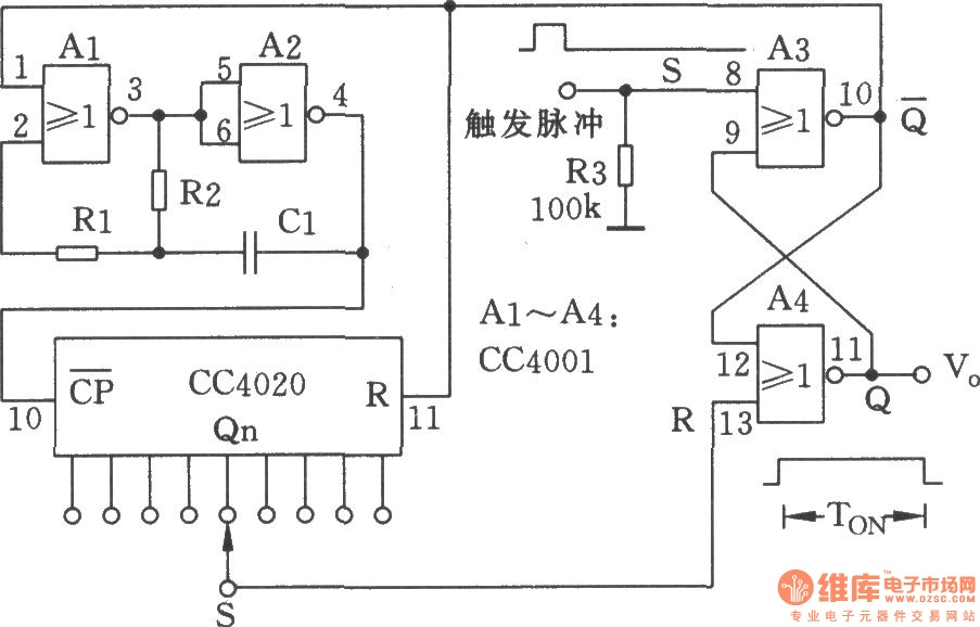
The NC monostable multivibrator circuit depicted in the chart consists of four 2-input NOR gates (CC4001) and a 14-bit binary serial counter/divider (CC4020). It is primarily utilized as a time delay switch or timer in automatic control equipment. The NC...
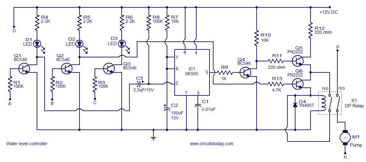
A simple water level controller circuit utilizing a 555 integrated circuit (IC) and six transistors. A relay is employed for controlling the pump motor. This water level controller circuit is designed to monitor and manage the water level in a...
This page discusses the various ways that a voltage regulator can be made using two transistors. If one of these transistors is the series-pass element, then the other must be the error amplifier, so there is a distinct limit...
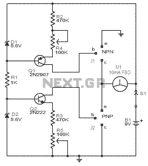
This circuit is a simple device for testing the hfe (current gain) of both PNP and NPN transistors, with the capability to measure hfe values as high as 1000. It operates using two constant current sources formed by transistors...
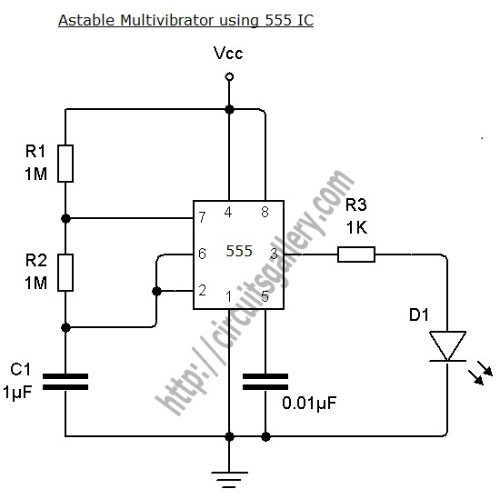
An astable multivibrator can be designed using a 555 timer IC, operational amplifiers, or transistors. The 555 timer IC provides accurate time delays ranging from milliseconds to hours, with the frequency of oscillation adjustable through simple modifications. This is...
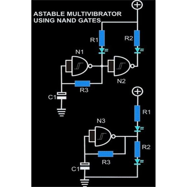
An astable multivibrator is an electronic configuration that generates continuous alternating high and low pulses from two outputs operating in tandem. The IC 4093 consists of four individual NAND gates in one package, specifically Schmitt trigger types, which provide...