
Astable Multivibrator using NE 555 timer IC

The astable multivibrator circuit based on the 555 timer operates in a continuous oscillation mode, generating a square wave output. The key components include two resistors (R1 and R2) and one capacitor (C1), which determine the frequency and duty cycle of the output waveform. The relationship between these components can be described using the formula for frequency:
\[ f = \frac{1.44}{(R1 + 2R2) \times C1} \]
This formula indicates that increasing the resistance values or the capacitance will decrease the frequency of oscillation. The duty cycle, which defines the proportion of time the output is high versus low, is influenced by the ratio of R1 to R2. For applications requiring specific duty cycles, careful selection of R1 and R2 is essential.
The 555 timer has two comparators internally that compare the voltage across the capacitor with predetermined threshold levels. When the voltage across C1 reaches 1/3 Vcc, the output of the lower comparator goes high, setting the flip-flop. Conversely, when the voltage reaches 2/3 Vcc, the upper comparator output goes high, resetting the flip-flop. This feedback mechanism ensures continuous oscillation.
The reset functionality provided by the fourth pin allows for external control of the timer operation. By applying a low signal to this pin, the timer can be effectively halted, which is useful for applications requiring synchronization or controlled timing sequences. The transistor Q2 acts as a switch, discharging the capacitor and ensuring the circuit can return to its initial state.
This astable multivibrator circuit is widely used in applications such as clock pulses generation, light flashers, tone generation, and frequency modulation. The simplicity of the 555 timer, combined with its versatility, makes it a popular choice for both educational purposes and practical electronic designs.Astable Multivibrator can be designed by using 555 timer IC, Op Amps and also using transistors. The 555 IC provide accurate time delay from mille seconds to hours. The frequency of oscillation can be controlled manually by simple modification. This is a simple 555 timer circuit project. Astable Multivibrator is simply an oscillator circuit that pr oduces continuous pulses. The frequency can be controlled by changing the values of R1, R2 and C1. When the capacitor voltage less than 1/3 Vcc, the lower comparator output will be high, then the control flip flop get set to High. (Q=1, Q`=0, Final output=1). 4th pin is Reset pin, a Low voltage at this pin resets the IC. The Low signal is applied to the base terminal of reset transistor Q2. Then it turns ON followed by Discharge capacitor Q1 and capacitor discharges. See the images below. 🔗 External reference
Related Circuits
This is an SCR timer circuit. In this circuit, an SCR is utilized to activate the final actuator, which is a buzzer. The time constant of the circuit is determined by resistor R1 and capacitor C1. The buzzer will...
This is a brief guide to help users begin with KiCAD. The tutorial focuses on a simple astable multivibrator circuit utilizing the 555 timer IC. The astable multivibrator circuit using the 555 timer IC is a fundamental electronic configuration that...
The circuit features two timing ranges: from 10 seconds to 5 minutes and from 1 minute to 80 minutes. It is powered by a 9-V battery. An LED is connected in a manner that allows for a consistent flashing...
A digital thermometer is being planned for construction using an ATmega8 microcontroller and an LM335 temperature sensor. Guidance is sought on how to proceed with the project, particularly concerning the display components. The digital thermometer circuit utilizes the ATmega8 microcontroller,...
Do not use the on-board relay to switch mains voltage. The board's layout does not provide adequate isolation between the relay contacts and the low-voltage components. If mains voltage switching is required, mount a suitably rated relay in a...
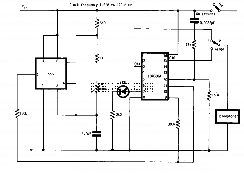
This simple alarm timer circuit is constructed using a 4060 IC, which features an integrated oscillator known for its good stability and relatively wide frequency range. The 4060 integrated circuit (IC) serves as the core component of this alarm timer...