
DC Motor Controller Circuit with NE555

The described circuit employs the NE555 timer IC in an astable configuration to generate a pulse-width modulation (PWM) signal, which is essential for controlling the speed of a DC motor. The NE555's output frequency and duty cycle can be adjusted to achieve the desired motor speed. The duty cycle is modified by changing the resistance of the potentiometer R1, allowing for fine-tuning of the motor's performance.
The transistor Q1 functions as a switch, responding to the PWM signal from the NE555. When the PWM signal is high, Q1 conducts, allowing current to flow through the motor, thereby powering it. The average voltage across the motor is directly proportional to the duty cycle of the PWM signal; a higher duty cycle means more time for the motor to receive power, resulting in increased speed. Conversely, a lower duty cycle reduces the average voltage, slowing the motor down.
To control the direction of the motor, a double-pole double-throw (DPDT) switch S1 is employed. This switch allows the user to reverse the polarity of the voltage supplied to the motor, effectively changing its rotation direction. When the switch is toggled, the connections to the motor terminals are reversed, causing the motor to spin in the opposite direction.
This circuit is suitable for various applications, including robotics, automation, and hobby projects, where precise control of motor speed and direction is required. The simplicity of the NE555 timer and the inclusion of a DPDT switch make this circuit an accessible option for both beginners and experienced electronics enthusiasts looking to implement motor control solutions.Welcome to the weblog where we discuss about electronic circuits schematics, PCB design, diy kits and electronic projects diagrams. A simple DC motor controller circuit with NE555 is shown here. several DC motor speed contro l circuits are revealed here however this can be the first one using NE555 timer IC.
additionally to controlling the motors speed its direction of rotation will be also modified using this circuit. A PWM circuit primarily based on timer NE555 is that the heart of this circuit. NE555 is wired as an astable multivibrator whose duty cycle will be adjusted by varying the POT R1. The output of IC1 is coupled to the base of transistor Q1 that drives the motor according to the PWM signal available at its base. Higher the duty cycle the typical voltage across motor will be high which ends in higher motor speed and vice versa.
modification of DC motor direction is attained using the DPDT switch S1 that on application simply toggles the polarity applied to the motor. 🔗 External reference
Related Circuits
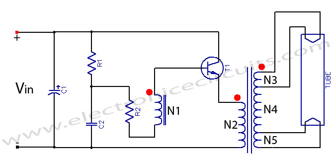
Fluorescent tube light circuit of an inverter that uses a single transistor and a single transformer. This type of inverter can be made in various configurations. The fluorescent tube light circuit described utilizes a basic inverter design that incorporates a...
This circuit is designed as a warning flasher to alert road users to dangerous situations in low-light conditions. It can also function as a bicycle light, subject to applicable traffic regulations. White LEDs are recommended for use as a...
Short circuits or broken PCB tracks can be easily identified using a multimeter. However, this tool may yield inaccurate results when assessing the efficiency of a transistor or diode unless the device is unsoldered and removed from the PCB....
This ultra-bright white LED lamp operates on 230V AC with low power consumption. It is suitable for illuminating VU meters, SWR meters, and similar applications. The ultra-bright LEDs available in the market range from Rs 8 to 15. These...
This is a non-contact power regulator circuit designed for a light load. By adjusting a 150kΩ potentiometer, phase shift can be achieved, and a trigger voltage is applied to the gate of a bidirectional thyristor through a bidirectional trigger...

After dismantling a Chinese copy of a Segway, an examination of the motor controller was conducted. After several hours of work with a multimeter, pen, paper, and KiCad, a block diagram and schematic of the motor controller were developed....