
Ultrasonic Mosquito RepellerCircuit by CD4017

The ultrasonic mosquito repeller circuit operates on the principle that certain high-frequency sounds, inaudible to humans, can deter mosquitoes and other pests. The core of the circuit is the CD4017, a decade counter that functions as a frequency generator when configured appropriately. The output frequency is crucial for the effectiveness of the device; thus, it is adjustable through the combination of capacitor C1 and resistor R1, along with the variable resistor VR1.
In this configuration, C1 determines the timing characteristics of the oscillation, while R1 and VR1 allow for fine-tuning of the frequency output. By altering the resistance, the time constant of the RC network changes, thereby modifying the frequency of the generated ultrasonic sound. The desired frequency range of 20 kHz to 25 kHz is pivotal, as this range has been identified as effective for repelling mosquitoes.
The circuit typically includes a power supply section that provides the necessary voltage to the CD4017, ensuring stable operation. An output stage, which may consist of a small speaker or piezoelectric transducer, converts the electrical signals into ultrasonic sound waves. Proper layout and component selection are essential to minimize interference and ensure that the ultrasonic waves are emitted efficiently.
Overall, this circuit represents an innovative approach to pest control, leveraging the properties of ultrasonic sound to create an environment less hospitable to mosquitoes without the use of chemicals or traps.This is a simple ultrasonic mosquito repeller circuit diagram. The circuit is design on the theory that pests like mosquito can be repelled by ultrasonic frequency around (20KHz-25KHz). This ultrasonic mosquito repeller circuit is based on a single CMOS IC CD4017. C1, R1 & VR1 is used to adjust the output frequency. 🔗 External reference
Related Circuits

This is the design circuit diagram of an ultrasonic mosquito repeller. The circuit operates based on the theory that insects, such as mosquitoes, can be repelled by sound frequencies in the ultrasonic range (above 20 kHz). The circuit utilizes...
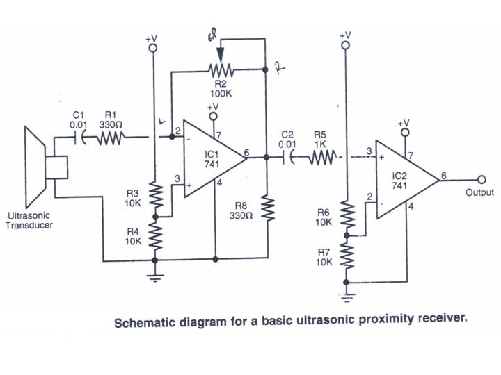
This section provides step-by-step instructions, accompanied by photos, for constructing an Ultrasonic Proximity Receiver. As this circuit is quite simple, only a schematic for the sensor is presented here. The objective of this tutorial is to assist others in...

This project has numerous practical applications in security and alarm systems for homes, shops, and vehicles. It consists of a set of ultrasonic receivers and transmitters operating at the same frequency. When movement occurs in the area monitored by...
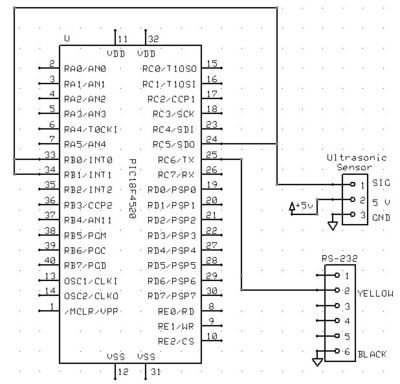
The Ping Ultrasonic Distance Sensor by Parallax features three pins: +5V, I/O, and Ground. To activate the sensor, a 5-microsecond 5V signal must be sent to the I/O pin. Following this, the sensor waits 750 microseconds before emitting an...
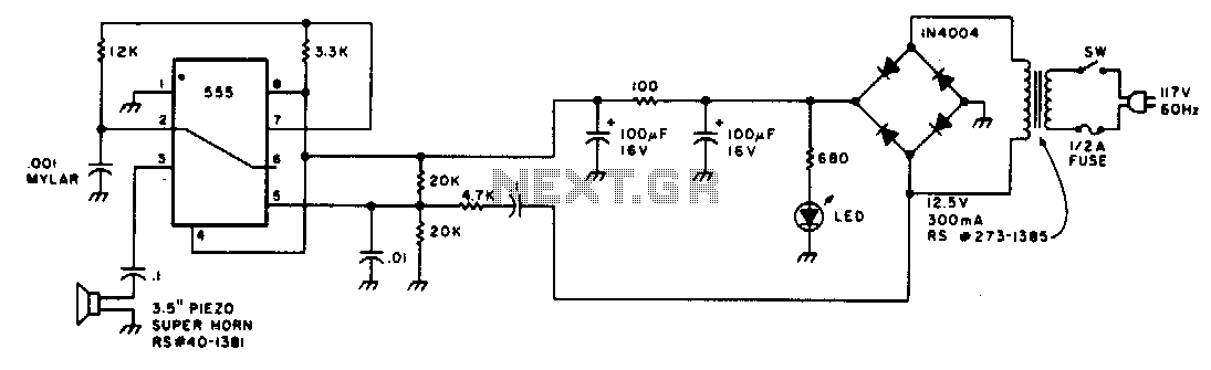
Low-intensity ultrasonic sound waves in the 30-45 kHz frequency band repel insects and small rodents. The unit is designed to generate a swept square wave from 30 to 45 kHz. The LM555 integrated circuit (IC) is configured as an...
The Diploma Final Year Project represents the culmination of the learning process, where it is essential to apply previously acquired engineering and personal skills. The assessment significantly influences decisions regarding readiness for graduation. This final year project spans an...