
AT89C4051 as RTC

The digital clock circuit utilizes the AT89C4051 microcontroller as the core component for real-time clock functionality. The AT89C4051 is an 8-bit microcontroller that is part of the MCS-51 family, featuring a 4KB flash memory, 128 bytes of RAM, and 32 I/O lines. In this design, Port 1 of the AT89C4051 is dedicated to interfacing with a 20x4 LCD display, where data is transmitted to the display for visualization of the time.
The LCD operates in 4-bit mode, allowing it to use only four data lines from Port 1, thus conserving I/O resources. The pins used for the LCD connection are typically defined as follows: RS (Register Select), RW (Read/Write), and E (Enable) are connected to specific control lines on the microcontroller. The remaining data pins, D4 to D7, are connected to Port 1 of the AT89C4051, starting from pin 7 to pin 14 of the LCD.
To enhance the display, the design incorporates the use of Character Generator RAM (CGRAM) within the LCD controller. This feature enables the creation of custom characters, which is particularly useful for displaying larger digits or unique symbols that are not available in the standard character set. The process of defining these custom characters involves writing specific patterns to the CGRAM, allowing the user to customize the appearance of the displayed digits.
The clock function is implemented through a timing mechanism, typically using a crystal oscillator connected to the microcontroller, which provides the necessary timing intervals for accurate timekeeping. The software running on the AT89C4051 is responsible for managing the timing, updating the LCD display, and handling user inputs if any buttons are included for setting the time.
Overall, this digital clock circuit effectively combines the capabilities of the AT89C4051 microcontroller with a flexible LCD display to create a user-friendly timekeeping device that can be customized to display information in a visually appealing manner.Its a digial clock which make use of AT89C4051 to work as a Real time clock. Port 1 of the controller (AT89C4051) is used as the data lines for the LCD (starting from pin 7- pin14 of LCD). As you can see there is not much change in the hardware except the LCD, here i am using a 20 x 4 lines LCD display.
In figure 3 as you can see the digits are bigger than the normal size. For this purpose i`m maiking use of the CGRAM of the LCD, which gives the flexibility to the user to define user defined characters. so to create a character we first need to get 🔗 External reference
Related Circuits
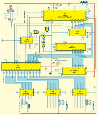
This project is based on the Atmel AT89C52 microcontroller and the Dallas real-time clock (RTC) chip DS12887. It can control and remotely program the switching operations of 24 electrically operated devices, allowing them to be turned on or off...
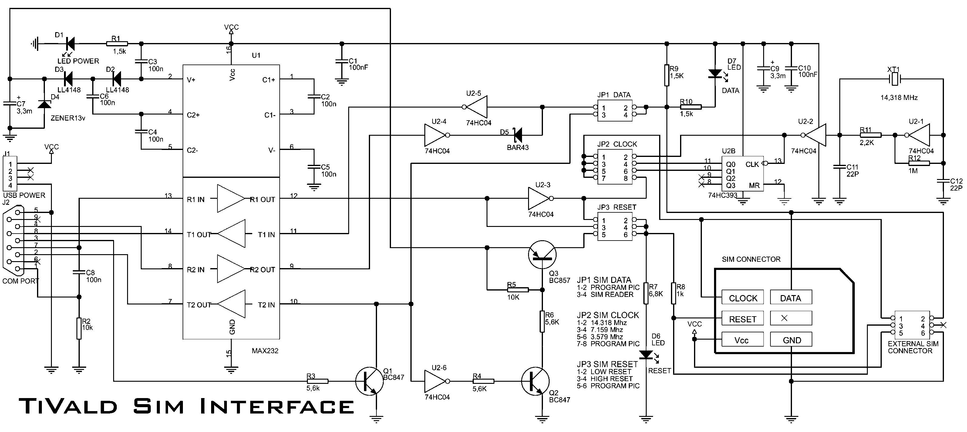
Pinout of a smart card (SIM card) to PC adapter cable (SIM reader/writer) schematic and layout of a 6-pin SIM card special connector and a 9-pin D-SUB female connector used to connect computers to ISO 7816 compatible chip card...
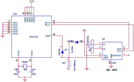
The I2C (Inter-IC) bus is a bi-directional two-wire serial bus that facilitates communication between integrated circuits (ICs). It is a synchronous protocol that enables a master device to initiate communication with a slave device, allowing data exchange between them....

A miniature real-time controller manages night lights, air conditioning units, and household appliances with a programmable scheduler. The device utilizes modified source code and a hex file for year 2002 readout. The circuit comprises three primary chips: an 89C2051...
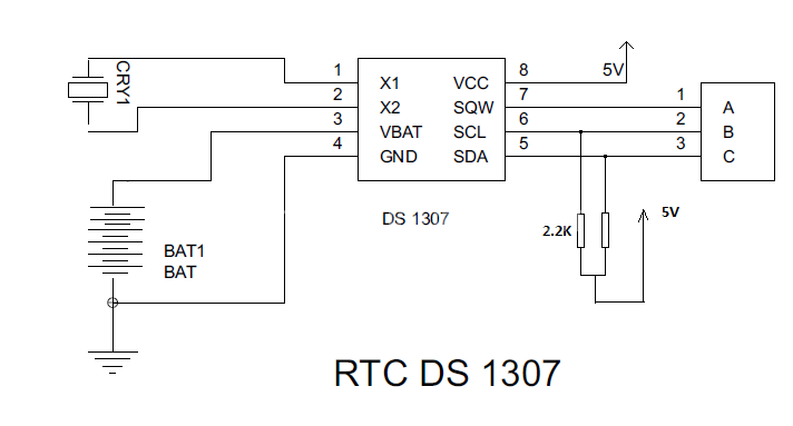
Steps involved in interfacing a Real-Time Clock (RTC) with a microcontroller. The RTC remains powered even when the device is turned off. The microcontroller must interface with the RTC to retrieve the data. To interface an RTC with a microcontroller,...
This smartcard adapter follows exactly the specification ISO 7816. Also, the protocol is the "asynchronous half duplex T=0 protocol" with "active low reset" and "inverse convention" as defined in this standard. The following description may be used in order...