
smartcard pc cable pinout.

The schematic for the SIM card to PC adapter cable is essential for establishing communication between a computer and ISO 7816 compliant smart cards, which are widely used in applications such as mobile telephony and digital television services. The layout involves two primary connectors: a 6-pin connector for the SIM card and a 9-pin D-SUB female connector that interfaces with the computer.
The 6-pin SIM card connector typically includes the following pin assignments:
1. **VCC** - The power supply pin that provides the necessary voltage to the SIM card.
2. **GND** - The ground connection, which serves as the reference point for the power supply.
3. **I/O** - The input/output pin used for data communication between the SIM card and the host device.
4. **RST** - The reset pin that initializes the SIM card.
5. **CLK** - The clock signal pin that synchronizes data transmission.
6. **VPP** - The programming voltage pin, which is used for specific operations during card programming.
The 9-pin D-SUB female connector connects to the computer and typically follows the standard RS-232 pinout configuration. The relevant pins include:
1. **Pin 1 (DCD)** - Data Carrier Detect.
2. **Pin 2 (RXD)** - Receive Data, which receives data from the SIM card.
3. **Pin 3 (TXD)** - Transmit Data, which sends data to the SIM card.
4. **Pin 4 (DTR)** - Data Terminal Ready, indicating that the device is ready to communicate.
5. **Pin 5 (GND)** - Ground connection for signal reference.
6. **Pin 6 (DSR)** - Data Set Ready, indicating that the SIM card is ready to communicate.
7. **Pin 7 (RTS)** - Request to Send, used to control data flow.
8. **Pin 8 (CTS)** - Clear to Send, indicating that the device can send data.
9. **Pin 9 (RI)** - Ring Indicator, used for signaling.
The connection between the SIM card and the computer allows for the reading and writing of data to the SIM card, enabling functionalities such as contact management, SMS operations, and application management. This schematic is crucial for developers and engineers working with smart card technology, ensuring proper interfacing and communication protocols are adhered to for reliable operation. Proper attention to the pin configuration and electrical characteristics is essential to prevent damage to the components and ensure optimal performance.Pinout of Smart card (Sim card) to PC adapter cable (sim reader/writer) schematic and layout of 6 pin Simcard special connector and 9 pin D-SUB female connectorused to to connect computers to ISO 7816 compatible chip card systems (e.g. GSM mobile phones or pay-TV decoding systems).. 🔗 External reference
Related Circuits
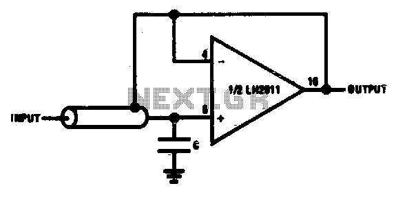
A bootstrapping input shield for a follower reduces cable capacitance, leakage, and spurious voltages resulting from cable flexing. Instability can be mitigated by using a small capacitor on the input. The bootstrapping input shield is a critical component in electronic...
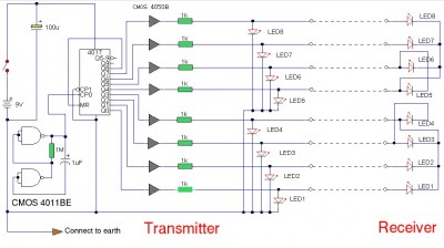
The LAN tester circuit can also test cables such as telephone, coaxial, LAN, and others. This circuit uses LEDs as the main indicator device. The LAN tester circuit is designed to verify the integrity and functionality of various types of...
First of all you have to build one cable adapter to connect the female 9pins connector of the modem, with female 9pins connector of the base of E-10G HPC. To build the null modem cable you will need: 2...
The TX audio cable can be more complex than the RX audio cable. Typically, the TX audio cable requires a circuit to reduce the voltage from the sound card's LINE OUT jack; otherwise, the radio's transmit circuit may be...
In need for a cheap but effective RS-232 Protocol Analyser? Just make your own Y adaptor to enable the logging or display of data transmitted and/or received in ASCII, Hex, Decimal or Hex-Dump formats. A configuration file is included...
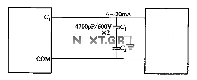
A capacitor filter is utilized in frequency control circuits and is a common method for implementing anti-jamming measures. It addresses frequency interference noise within the wiring of the 4-20mA control loop. The anti-interference is achieved through bypass capacitors C1...