
AUDIBLE LIGHT SENSOR

The circuit employs the 741 op-amp in an astable multivibrator configuration, where the oscillation frequency is primarily determined by the feedback network comprising the photocells. The two photocells, PC1 and PC2, are positioned strategically to respond to varying light conditions, thus modulating the output frequency of the audio oscillator.
In this setup, PC1 and PC2 are used to influence the gain of the op-amp based on the light intensity they receive. Specifically, PC1 is placed in the feedback loop, where its resistance changes inversely with light intensity. This change alters the feedback factor, which directly affects the oscillation frequency produced by the op-amp. As light intensity on PC1 increases, its resistance decreases, thus reducing the feedback and resulting in a lower frequency output.
On the other hand, PC2 is connected to the non-inverting input of the op-amp. As light strikes PC2, its resistance decreases, which increases the voltage at the non-inverting input. This increase in voltage raises the output frequency of the oscillator. The interaction between these two photocells allows for a dynamic range of audio frequency modulation based on the ambient light conditions.
The choice of resistor R4 is critical in determining the time constant of the circuit, which in turn affects the overall frequency range of the audio output. Proper selection of R4, along with the characteristics of the photocells, will enable the circuit to produce a desired range of audio frequencies suitable for various applications, such as sound synthesis or educational demonstrations of light-to-sound conversion. It is essential to ensure that the power supply voltage for the 741 op-amp is within the specified limits to maintain stable operation and prevent distortion in the output signal.741 opamp is connected as audio oscillator with Radio Shack 276-677 photocells in feedback circuits. When light strikes PC1, its resistance decreases and frequency of audio tone in headphone decreases correspondingly. When light strikes PC2, which is connected to noninverting input of 741, increase in illumination serves to increase frequency.
Choose R4 to r.. 🔗 External reference
Related Circuits
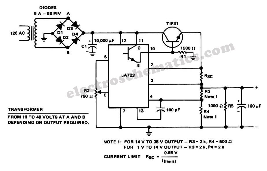
The diagram illustrates the circuit of a versatile USB power socket that safely converts 12V battery voltage into a stable 5V output. This circuit enables the use of various USB-powered devices. The circuit design consists of several key components to...
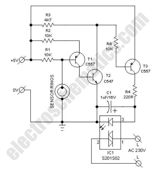
This compact water sensor alarm circuit emits a loud warning sound when a humidity sensor detects the presence of water. The circuit utilizes the low-power comparator LM1801 from National Semiconductor. A fixed reference voltage for the integrated circuit is...
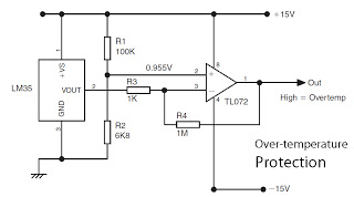
This is a basic overview of the LM35 temperature sensor, which is interfaced with an operational amplifier (op-amp) to boost its output. The LM35 provides a high output voltage when it detects high temperatures. The output can be utilized...
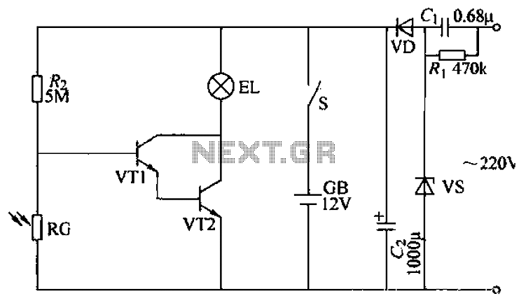
The power supply circuit features a step-down capacitor (C1), bleeder resistors (R), a Zener diode (VS), a full diode (VD), and a filter capacitor (G), along with switches and batteries (GB, SC). The light control circuit is composed of...
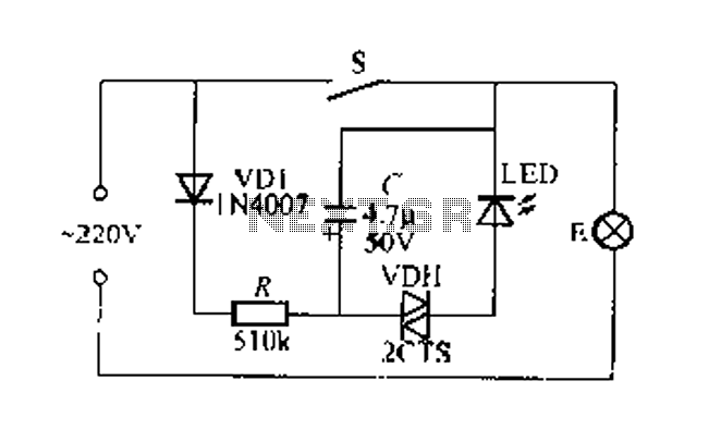
Figure 2 illustrates a circuit for a flashing light switch indicator. When switch S is closed, the normal light E illuminates, while the flashing light indicates a power loss when the system is not operational. When switch S is...
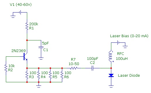
The speed of light has been measured using various ingenious methods. This note describes a conceptually simple and relatively easy-to-implement technique known as the time-of-flight optical pulse delay method. It utilizes a short (nanosecond) optical pulse and an oscilloscope...