
Flashing light indicates the light switch circuit

The circuit operates on the principle of providing a visual indication of the operational status of a lighting system. The primary component, the switch S, controls the flow of current through the circuit. When S is closed, the circuit is energized, allowing lamp E to light up, indicating normal operation. The inclusion of the rectifier diode VD1 ensures that the AC voltage is converted to a suitable form for charging capacitor C, which stores energy for the oscillation process.
Resistor R plays a crucial role in limiting the current that charges capacitor C, preventing damage to the components and ensuring stable operation. The relaxation oscillator is formed by the interaction between capacitor C and the bidirectional trigger diode VDH. As the capacitor charges and discharges, it creates a pulsing effect that causes the LED (light-emitting diode) to flash. The flashing light serves as an effective indicator, especially in low-light conditions, allowing users to easily identify the switch's location.
In the event of a power outage, if switch S is activated and the LED does not light up, this indicates that the main bulb E has failed, thereby alerting the user to check the bulb. The VDH diode is selected for its ability to trigger at a specific voltage range, making it suitable for this application. The use of a high-brightness red LED ensures maximum visibility, enhancing the overall functionality of the circuit. This design is particularly useful in residential and commercial settings, where reliable indicators of power status are essential for safety and convenience.Figure 2 foot emitting a flashing light switch circuit indication. when s is closed, normal light E lights flashing hair light indicates power loss of power does not work shoes . Open after s. 220V AC by lamp E and a rectifier diode VD1, R buck limit the flow of the charging capacitor c. Negative zoot Sui and capacitance C of the present circuit utilizes two-way trigger diode VDH of charge and discharge principle can constitute a relaxation oscillator, so luminous tube I, ED will flashing light at night is very eye-catching, makes it easy to find switch position. If s beat Ji, LED small light, not the light bulb filament E blown, it is a power outage. VDH may be a turning point in the voltage range of 20-40V bidirectional trigger diodes as 2CTSIA, DB3 type.
I.ED most tincture high-brightness red light emitting diodes.
Related Circuits
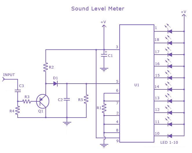
This is a single-chip sound level meter that can be used to display the sound level of an amplifier or simply the sound level from a microphone. The core component of the circuit is the IC LM3915 Audio Level...

Project with Circuit and Code for a Typing Assistant using the 8051 microcontroller (AT89S52) and the PS/2 keyboard port of a computer. The project also explains the interfacing of the PS/2 port of a computer with the 8051 microcontroller. The...
The ultrasonic signal received by the reception sensor is amplified by a factor of 1000 (60 dB) using a two-stage operational amplifier. The first stage provides a gain of 100 (40 dB), while the second stage offers a gain...

The ultrasonic anti-collision circuit is designed using the LM1812 integrated circuit, which controls both the transmission and reception functions. A distance control potentiometer allows for adjustments within a range of 2 to 3 meters. The timebase circuit is constructed...
This circuit triggers an alarm when its LDR (Light Dependent Resistor) sensor is exposed to light from the sun or a lamp. A 555 astable multivibrator is utilized to generate a tone of approximately 1 kHz upon detecting light....

The device is referred to as the Itsy Bitsy USB Lamp. This concept is remarkably straightforward, raising the question of why it had not been conceived earlier. Originating as a student project at Massey University in Wellington, New Zealand,...