
DARLINGTON LOGIC PROBE
The two-transistor Darlington configuration consists of two bipolar junction transistors (BJTs) arranged such that the emitter of the first transistor is connected to the base of the second. This arrangement effectively amplifies the input current, resulting in a significant increase in the overall current gain of the circuit. The high input impedance characteristic of this configuration is particularly advantageous in applications where it is essential to monitor logic circuits without introducing additional load, which could alter the circuit's performance.
In this setup, the input signal is applied to the base of the first transistor. When a logic high signal (logic 1) is present, the first transistor turns on, allowing current to flow from its collector to its emitter. This action provides sufficient base current to the second transistor, which also turns on, allowing a larger current to flow through the collector-emitter path of the second transistor. The output of this Darlington pair can be connected to an LED. When the second transistor is activated, it completes the circuit for the LED, causing it to glow, thereby providing a visual indication of the logic state.
The circuit typically requires a current-limiting resistor in series with the LED to prevent excessive current from damaging the LED. The value of this resistor can be calculated based on the forward voltage of the LED and the supply voltage used for the circuit. It is also important to ensure that the transistors selected can handle the expected current and voltage levels within the application.
This Darlington pair configuration is widely used in various electronic applications, including signal amplification, switching, and interfacing between different logic levels, making it a versatile choice for experimenters and engineers alike.Two-transistor Darlington connection provides very high input impedance that does not load logic circuit being monitored, while driving LED that glows when logic 1 is present at input.-F. M. Mims, Computer Circuits for Experimenters, Radio Shack, Fort Worth, TX, 1974, p 35-43.. 🔗 External reference
Related Circuits
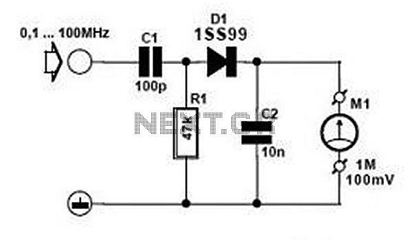
Comprehensive information about RF Probe Circuits is available. Users can learn about and download RF Probe Circuit designs online. RF Probe Circuits are essential tools for testing and analyzing radio frequency signals in various applications, including telecommunications, broadcasting, and electronic...
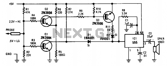
The probe's input circuit detects the signal condition and generates a low-pitched tone for low-level signals (below 0.8 V) or a high-pitched tone for high-level signals (above 2 V). The tone probe employs sound to indicate the status of...
This tester is designed to locate stray electromagnetic (EM) fields. It can easily detect both audio and RF signals up to frequencies of around 100 kHz. However, it is important to note that this circuit is not a metal...
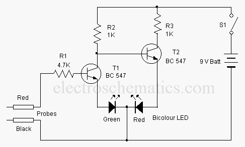
This is a basic logic state indicator designed to test whether the output of a digital integrated circuit (IC) is in a logic high (1) or logic low (0). The bicolor LED illuminates green when the logic state is...
This tester is designed to locate stray electromagnetic (EM) fields. It can easily detect both audio and RF signals up to frequencies of around 100 kHz. However, this circuit is not a metal detector, but it can detect metal...
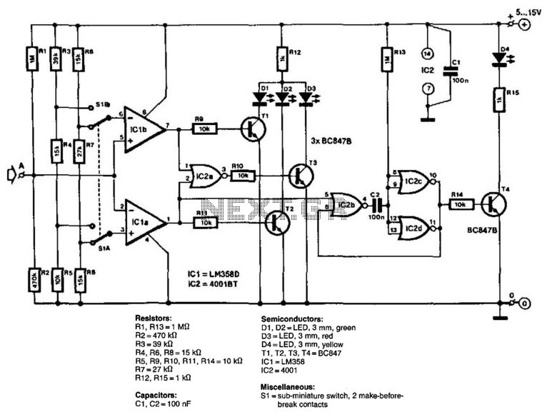
The circuit consists of two comparators that operate with different reference voltages supplied by separate potential dividers. Divider R3/R4/R5 provides a voltage of approximately 40% of the supply voltage (Ucc) to pin 6 of IC1B and about 16% of...