
Audible ttl probe

The described circuit operates as a simple audio output device that responds to digital logic levels. It utilizes a probe mechanism to detect TTL (Transistor-Transistor Logic) signals. The probe's function is to provide auditory feedback based on the logic state detected at its tip.
The circuit comprises a small audio oscillator, which generates sound frequencies corresponding to the logic levels. When the probe touches a point in the circuit that outputs a TTL low (0), the audio oscillator produces a low-frequency tone. This is typically achieved using a simple transistor-based oscillator or a dedicated audio IC configured to generate low frequencies. The frequency of the sound produced is determined by the components used in the oscillator circuit, such as resistors and capacitors.
In the case of a TTL high (1) signal, the circuit responds by generating a high-frequency tone. This can be accomplished by switching the oscillator's configuration or using a different oscillator circuit that is designed to produce higher frequencies. The transition between low and high tones provides a clear auditory indication of the detected signal state.
Powering the circuit from the circuit under test allows for portability and ease of use, as it eliminates the need for an external power source. The circuit must be designed to handle the voltage levels present in the circuit under test, typically ranging from 0 to 5 volts for TTL logic levels. Proper isolation and protection mechanisms should be implemented to prevent damage to the probe or the circuit under test.
Overall, this circuit serves as a practical tool for troubleshooting and testing digital circuits, providing immediate feedback through sound to indicate the state of the logic levels being probed.When the probe is in contact with a TTL low (0) the probe emits a low note. With a TTL high (1), a high note is emitted Power is supplied by the circuit under test.
Related Circuits
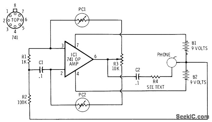
The 741 operational amplifier is configured as an audio oscillator using Radio Shack 276-677 photocells in the feedback circuits. When light strikes photocell PC1, its resistance decreases, resulting in a corresponding decrease in the frequency of the audio tone...
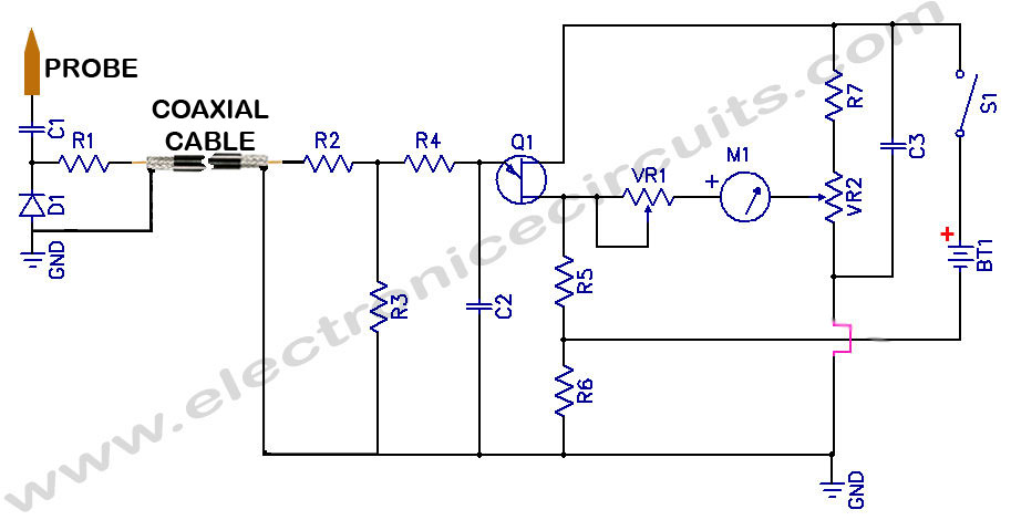
Sensitive RF Voltmeter Probe Circuit. This circuit measures RF voltages beyond 200 MHz and up to approximately 5V. The sensitive RF voltmeter probe circuit is designed to accurately measure radio frequency (RF) voltages in the range exceeding 200 MHz,...
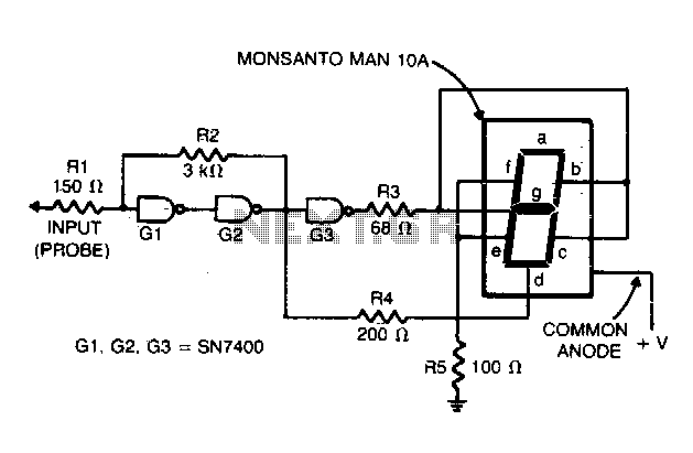
Gates G1 and G2, along with resistors R1 and R2, create a straightforward voltage monitor with a trip point set at 1 volt. Gate G3 functions as an inverter. The display section of the tester features a common anode...
This is a simple circuit of a Logic Probe for tri-state logic. This circuit can be built in just a few hours. Additionally, this circuit has other features. The Logic Probe circuit for tri-state logic is designed to detect and...
This tester is designed to locate stray electromagnetic (EM) fields. It will easily detect both audio and RF signals up to frequencies of around 100kHz. Note, however that this circuit is NOT a metal detector, but will detect metal...
This logic probe utilizes a single CMOS integrated circuit (IC) to indicate three logic states: High, Low, and Pulsing. If the probe input is in a high impedance state, which occurs when it is not connected to a circuit,...