
Ttl logic tester

The circuit utilizes two logic gates, G1 and G2, to monitor the input voltage. Resistors R1 and R2 are configured to establish a voltage divider that determines the trip point at which the circuit will respond. When the input voltage crosses the threshold of 1 volt, the output from these gates will change state, effectively signaling the inverter gate G3. The inverter then alters the signal, ensuring that a high input voltage results in a low output and vice versa.
The output of gate G3 is connected to a common anode alphanumeric LED, which is designed to visually indicate the logic level. The current-limiting resistors are essential to prevent excessive current from flowing through the LED, thereby protecting it from damage and ensuring proper functioning.
When the input voltage is above 1.4 V, the circuit outputs a high signal, illuminating the LED to display 'H'. Conversely, if the input voltage drops below this threshold, the output becomes low, and the LED displays 'L'. This simple yet effective voltage monitoring circuit is suitable for various applications where voltage levels need to be visually indicated, making it a valuable tool in electronic diagnostics and testing.Gates Gl and G2 together with resistors Rl and R2 form a simple voltage monitor that has a trip point of 1 volts. Gate G3 is simply an inverter. The display section of the tester consists of a common anode alphanumeric LED and current-limiting resistors
It indicates whether the input voltage is above or below 1,4 V, and displays a H or a L (for high or low logic-level) respectively.
Related Circuits
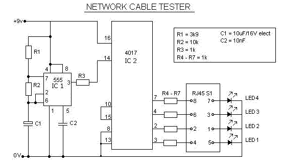
This is a multifunction RJ45 network cable tester designed for testing network cables (RJ45) and telephone cables (RJ11). It is cost-effective and user-friendly. The tester determines whether a network cable is a crossover or straight type by illuminating a...
Is the battery empty, or is there something wrong with the device? This question can be challenging when a battery-powered device, such as a Walkman, appears to be non-functional upon switching it on. Before seeking professional servicing, the initial...

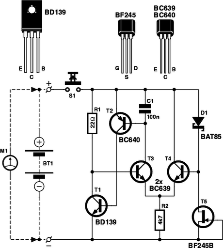
This circuit conducts a rapid battery test without requiring an external power supply or costly moving-coil voltmeters. It offers two testing ranges: when switch SW1 is configured as indicated in the circuit diagram, it can evaluate batteries ranging from...

The circuit does not guarantee the testing of all defective MOSFETs or all fault conditions in MOSFETs. If the MOSFET is functional, it will operate within the astable multivibrator circuit, resulting in the LED flashing. The described circuit employs an...
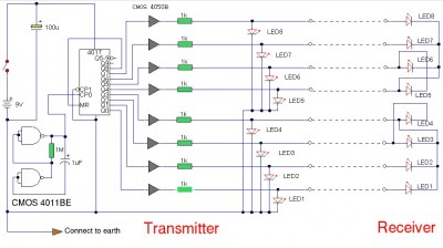
The LAN tester circuit can also test cables such as telephone, coaxial, LAN, and others. This circuit uses LEDs as the main indicator device. The LAN tester circuit is designed to verify the integrity and functionality of various types of...
There have been a lot of transistor tester circuits in recent electronics magazines, but this one is different. It has more features and includes a signal injector so you can test audio sections of radios and the front end...