
Audio Amplifier Output Relay Delay

This circuit employs a simple relay control mechanism suitable for audio applications where speaker protection is essential. The use of capacitors C1 and C2 in conjunction with resistors R1 and R2 provides the necessary timing characteristics. The charging and discharging rates of the capacitors dictate the delay before the speakers are engaged and disengaged, respectively.
In practical implementation, C1 acts as a power supply filter, ensuring stable voltage levels during operation, while C2's charging time defines the delay before the relay engages. The choice of the relay is crucial; it must be rated appropriately for the output voltage and current of the amplifier to ensure reliable operation. Transistors Q1 and Q2 serve as signal amplifiers and switches, controlling the relay based on the voltage levels across C2.
For applications requiring a more precise delay, the circuit could be enhanced by incorporating a microcontroller or timer IC, which would allow for more accurate timing and additional features such as adjustable delay settings. Nevertheless, the simplicity of this design makes it an appealing choice for DIY enthusiasts and those looking for a straightforward solution to speaker control in audio systems.This is a simple circuit which I built to one of my audio amplifier projects to control the speaker output relay. The purpose of this circuit is to control the relay which turns on the speaker output relay in the audio amplifier.
The idea of the circuit is wait around 5 seconds ofter the power up until the speakers are switched to the amplifier ou tput to avoid annoying "thump" sound from the speakers. Another feature of this circuit is that is disconnects the speaker immediately when the power in the amplifier is cut off, so avoiding sometimes nasty sounds when you turn the equipments off. Then power is applied to the power input of the circuit, the positive phase of AC voltage charges C1.
Then C2 starts to charge slowly through R1. When the voltage in C2 rises, the emitter output voltage of Q1 rises together with voltage on C2. When the output voltage of Q2 is high enough (typically around 16. 20V) the relay goes to on state and the relay witches connect the speakers to the amplifier output. It takes typically around 5 seconds after power up until the relay starts to conduct (at absolute time depends on the size of C2, relay voltage and circuit input voltage). When the power is switched off, C1 will loose it`s energy quite quickly. Also C2 will be charged quite quickly through R2. In less than 0. 5 seconds the speakers are disconnected from the amplifier output. This circuit is not the most accurate and elegant design, but it has worked nicely in my small home-built PA amplifier.
This circuit can be also used in many other applications where a turn on delay of few seconds is needed. The delay time can be increased by using bigger C2 and decreased by using a smaller C2 value. Note that the delay is not very accurate because of simplicity of this circuit and large tolerance of typical electrolytic capacitors (can be -20%.
+50% in some capacitors). Be the first of your friends to get free diy electronics projects, circuits diagrams, hacks, mods, gadgets & gizmo automatically each time we publish. Your email address & privacy are safe with us ! 🔗 External reference
Related Circuits
A very long time constant is provided by R1 and C1. C1 discharges, and the near-zero voltage at its positive lead is applied to the high-impedance inputs of the circuit. In this circuit, the combination of resistor R1 and capacitor...
A simple stereo amplifier with minimal external components. It utilizes only one operational amplifier, which is capable of delivering an output power of 2x5W into a 4-ohm load, with a distortion of 0.5%. This stereo amplifier circuit is designed to...
There is a project involving an Arduino that outputs audio signals to USB speakers using 10-bit PWM. Initially, the sound quality produced via PWM was unsatisfactory due to the limited processing speed of the Arduino, which is insufficient for...
A 100W amplifier with a frequency range from DC to 500KHz features a photoelectric starting operational amplifier with high input impedance and high gain characteristics, enabling transformerless output power of 100W. The load current can reach up to 10A,...
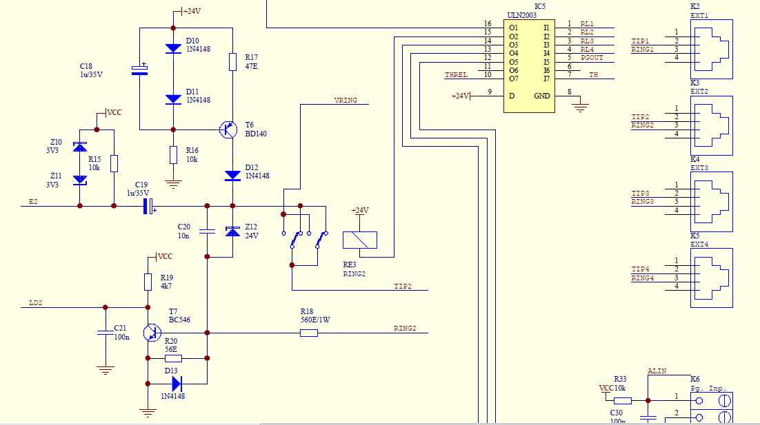
Create a simple telephone-based intercom system in a new house. Shouting between rooms is not effective, and using an instant messaging client or FaceTime lacks the immediacy of a voice call. A collection of old wired telephones is available...
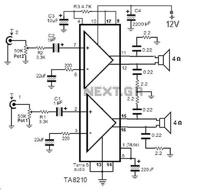
This circuit consists of a 2 x 22 watt BTL amplifier utilizing the IC TA8210AH. It functions not only as an automobile amplifier but is also suitable for low-frequency sound applications, particularly in high-fidelity audio systems, due to its...