
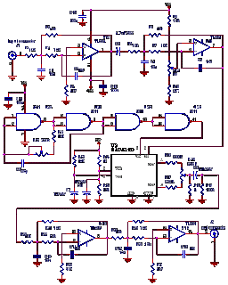
audio peak level indicator by op amp

The described circuit functions as a visual audio level indicator using three LEDs to represent different input signal levels. The resistors R3 to R7 are selected to ensure that LED D1 lights up at a nominal input level of 0 dB, corresponding to 0.775V RMS. As the input signal increases to +5 dB (1.378V RMS) and +10 dB (2.451V RMS), LEDs D2 and D3 illuminate, respectively. This functionality allows users to easily monitor audio levels, ensuring that signals remain within an acceptable range without distortion.
The circuit's design prioritizes low power consumption, making it suitable for battery-operated applications. This is particularly important in portable devices where battery life is a critical factor. To achieve optimal performance, two different operational amplifier (op-amp) types are employed: the LM393 and the LM324. The LM393 is primarily used for its low power characteristics but has limitations in driving the LEDs effectively in dot-mode. Conversely, the LM324, while more capable in terms of linear charging of capacitor C2, does not offer the same efficiency as the LM393 in this context.
The decision to utilize both op-amps, despite some inefficiencies, is justified by the overall energy savings achieved during operation. The added cost associated with using two op-amps is offset by the reduced current draw, leading to longer battery life. This design demonstrates a practical balance between functionality and efficiency, making it a valuable solution for applications requiring reliable visual indicators of audio signal levels.No setup is required: if correct values are used for resistors R3 to R7, LED D1 will illuminate at 0dB input (0. 775V RMS), LED D2 at +5dB input (1. 378V RMS) and LED D3 at +10dB (2. 451V RMS). The circuit was optimized for low current consumption as it was intended for battery operation. To achieve this, the best arrangement has proven to be the one using two different op-amp types for IC1 and IC2. In fact the LM393 IC was not operating satisfactorily as dot-mode LED driver, whereas the LM324 was unable to charge C2 in the linear way, as expected. Therefore, the final circuit is some op-amp wasting, but the small added cost will be quickly compensated by battery savings.
🔗 External reference
Related Circuits
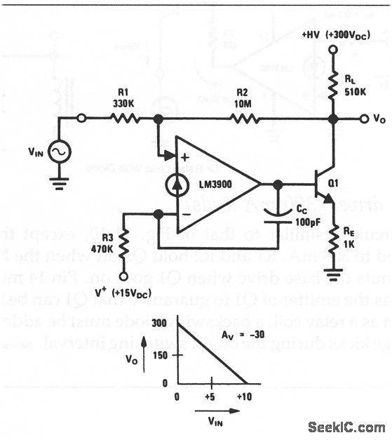
This circuit is an inverting amplifier with an output voltage swing from approximately 0 to +300 V. Any transistor can be utilized for Q1, as long as the breakdown voltage exceeds 300 V (since the full high voltage will...

12V Battery Charge Nominal Discharge (Low) Indicator Circuit. This circuit monitors car battery voltage and provides an indication of nominal supply voltage, as well as low or high voltage. The 12V Battery Charge Nominal Discharge Indicator Circuit is designed to...
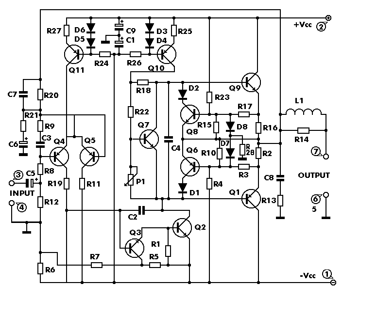
The circuit works from a symmetrical -40 VDC power supply and draws a maximum current of 2.6 A. The input circuit of the amplifier is a differential amplifier built around Q4 and Q5 that employ DC feedback thus preventing...
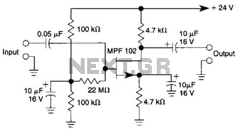
In this amplifier circuit, the gate of the MPF 102 is biased with an external voltage. This circuit achieves tighter control of the operating point and biasing conditions. The amplifier circuit utilizing the MPF 102 field-effect transistor (FET) is designed...
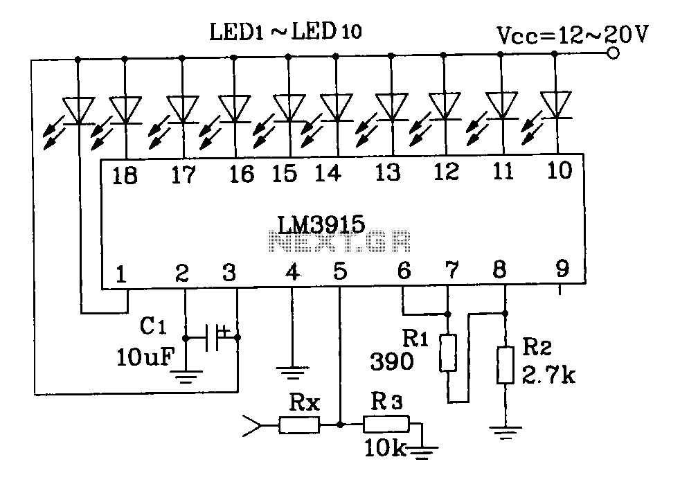
This document describes a simple LM3915 audio power meter circuit diagram. It notes that if the internal resistance of the speaker is 4 ohms, a resistor value of 10k ohms should be used for Rx. For an 8-ohm speaker,...
Utilizing an analog audio line delay, it is possible to virtually adjust the size of a room. By simply turning a knob on the audio equipment, one can modify the perceived room size. The circuit described herein facilitates this...