
Schematic Diagram LM35 Smart Heater Controller Project

The LM35 temperature sensor (IC1) is a precision device that provides an analog output voltage proportional to the temperature in degrees Celsius. The output voltage typically ranges from 0 mV at 0°C to 10 mV per degree Celsius. This characteristic allows for easy interfacing with the BiMOS Op-amp CA3140 (IC2), which is configured to amplify the output signal from the LM35. The op-amp can be set up in a non-inverting configuration to enhance the sensitivity of the temperature measurement.
The CA3140 is selected for its high input impedance and low offset voltage, making it suitable for precision applications. The op-amp's output is connected to the gate of the Triac BT136 (T1), which acts as a solid-state switch. When the temperature sensed by the LM35 exceeds a predetermined threshold, the op-amp output will trigger the Triac, allowing current to flow through the connected resistive heating element.
The Triac BT136 is capable of handling high power levels, making it ideal for controlling heating devices. Its ability to conduct current in both directions allows for efficient control of AC loads, which is essential in heating applications. Proper snubber circuits may be incorporated to protect the Triac from voltage spikes and ensure reliable operation.
Overall, this schematic provides a straightforward solution for temperature-controlled heating applications, combining the precision of the LM35 with the robust switching capabilities of the BT136 Triac, all regulated by the CA3140 op-amp.LM35 Smart Heater Controller SchematicMinuscule circuit of the electronic heater controller presented here is built around the renowned 3-Pin Integrated Temperature Sensor LM35 (IC1) from NSC. Besides, a popular BiMos Op-amp CA3140 (IC2) is used to sense the status of the temperature sensor IC1, which also controls a solid-state switch formed by a
high power Triac BT136(T1). Resistive type 🔗 External reference
Related Circuits

For this LED driver electronic project, a DC power supply circuit is required to provide an output voltage between 2.7V and 5.5V. The supply voltage must be applied between Vin and GND. The T/F jumper connects the T post...

The circuit operates without isolation for both input and output voltage, utilizing a working switch along with an inductor (L), diode (D), and capacitor (C) to form a basic inverter circuit. There are three types of converters: the step-down...
When an individual touches the safety box or other protected metal objects, the sensor circuit generates a pulse to the alarm circuit. The positive edge of this pulse activates the semiconductor and thyristor flash GE, subsequently triggering the camera...
Every electronic device that boosts electrical signals can be called an amplifier. The various amplifier types only differ in some specific features. Amplifiers are crucial components in electronic circuits, designed to increase the amplitude of electrical signals. They play a...

The circuit includes a momentary switch S1 that triggers an alarm pulse for the decade counter IC2, which increments its count with each alternating alarm pulse or the activation of switch S1. Ten variable resistors (VR1 through VR10) are...
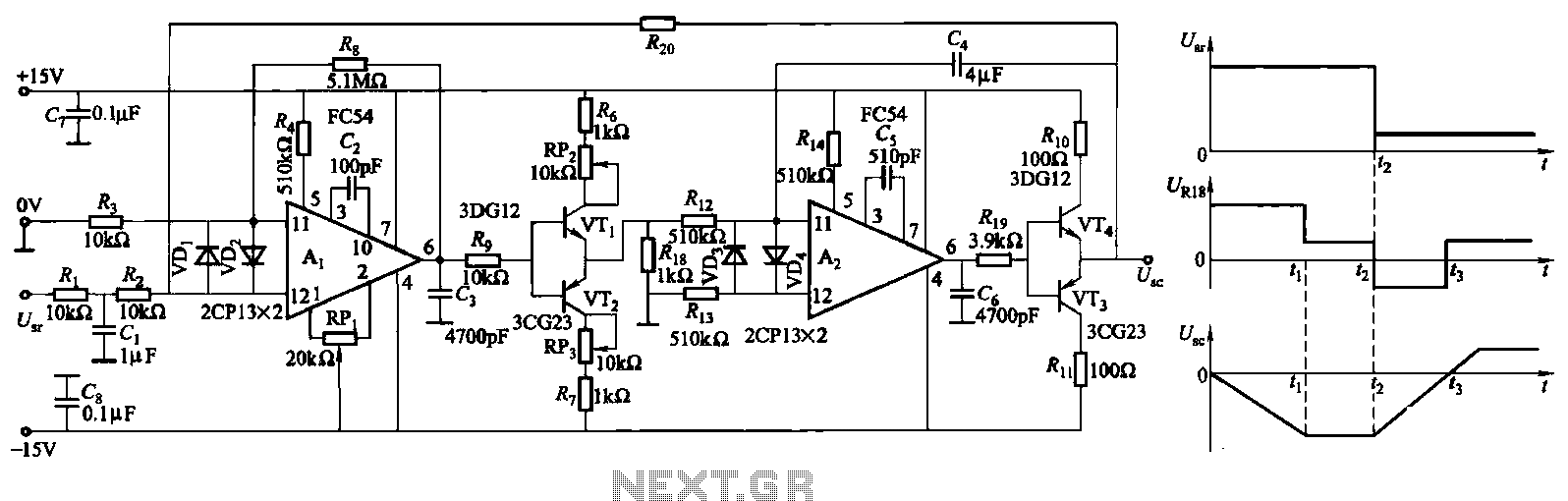
The ZKJ-S-type buffer controller circuit is designed for motor starting slip control. This buffer controller is composed of two operational amplifiers, Ai and Az. The operational amplifier Ai functions as a speed amplifier that saturates, while Az acts as...